Weld Drawing Symbols
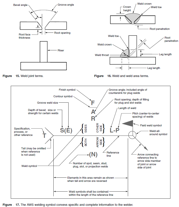
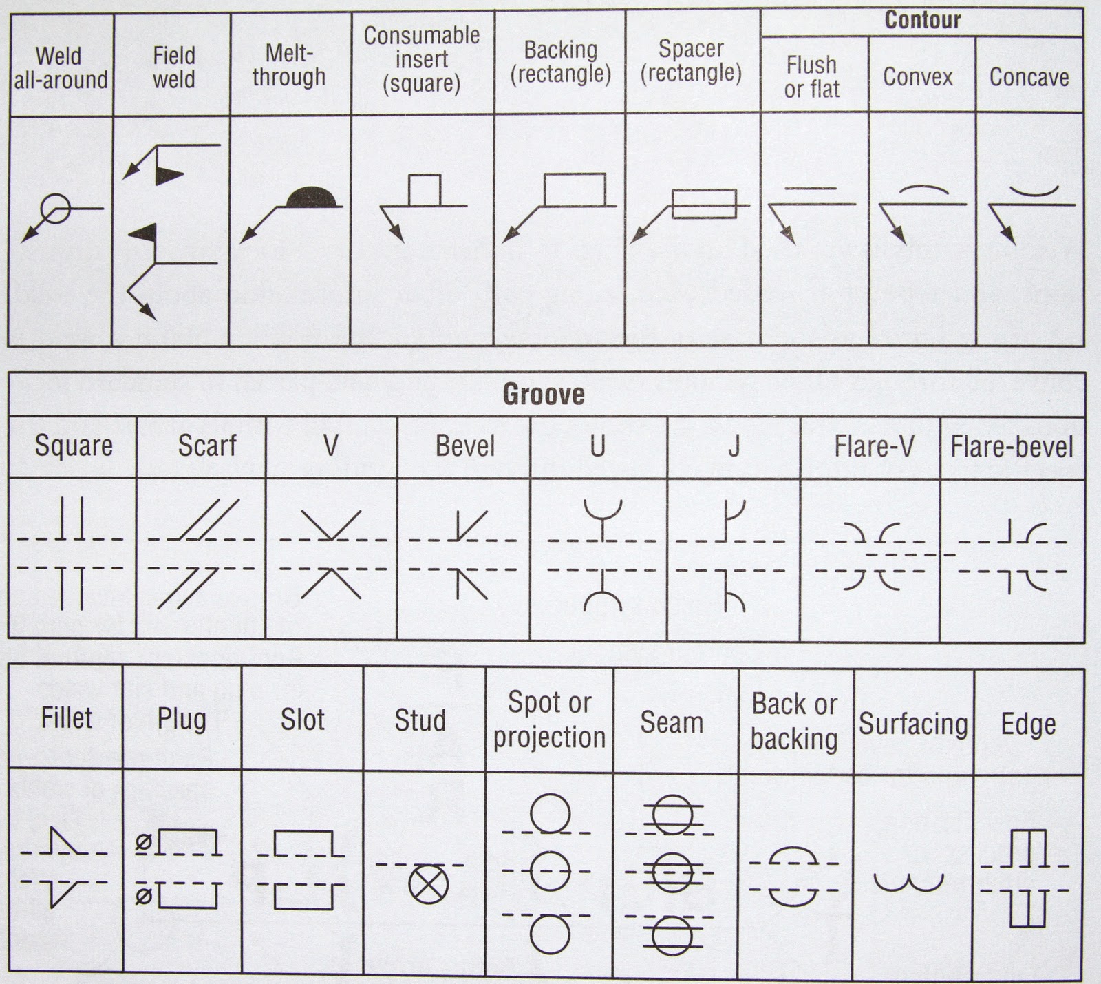
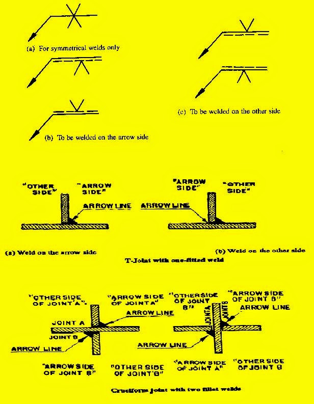
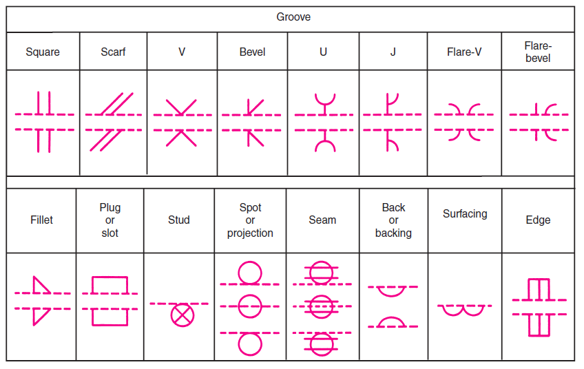
Weld Drawing Symbols - Location of this information matters. The arrow points at the joint where the weld will be placed, while information about the orientation and type of weld will be included along the arrow side, or reference line. 2.4 the orientation of the weld. Provides information like what kind of bevel should be prepared for welding ? Web the standards specify clear rules for the placement of weld symbols, dimension symbols, and dimension values on the reference line. A symbol can be used to specify the weld type, groove design, welding process, face & root contour, weld length, throat size, and other information. When you see an engineering fabrication drawing, you will notice several welding symbols on the drawing. All the information you need as a welder is in the welding symbol. Information such as size, length and other special considerations will be displayed next to the weld symbol. This is typically placed near the center of the reference line (and above or below it, depending on which side of the joint it's on). When creating welding diagrams, these rules must be strictly followed. Web welding symbols are extensively used in engineering drawings to explain information like weld size, type, location, and other supplementary information. Provides information like what kind of bevel should be prepared for welding ? Fillet weld symbols will always have the vertical line of the symbol on the left. Web. When creating welding diagrams, these rules must be strictly followed. When you see an engineering fabrication drawing, you will notice several welding symbols on the drawing. Whenever two or more pieces are joined by welding, the assembled item is called a weldment. Web welding symbols are the integral part and the basic requirements for fabrication as they provide vital information. Web types of welds and their symbols. Web welding symbols are the integral part and the basic requirements for fabrication as they provide vital information for the welding joint location, weld size (throat or leg length, depth of penetration) & length, weld type & quality requirements for the fabrication or construction drawing. How do you read welding symbols? Web the. Web welding symbols are used on drawings of parts and assemblies that are joined together by welding. Web welding symbols are extensively used in engineering drawings to explain information like weld size, type, location, and other supplementary information. Fillet weld symbols will always have the vertical line of the symbol on the left. Web the fabrication drawings includes welding symbols,. Each weld symbol is explained individually, with its weld profile alongside it. Web common weld symbols. Whenever two or more pieces are joined by welding, the assembled item is called a weldment. Web weld symbols are graphical representations used on engineering drawings to convey essential information about welded joints and welding processes. Web by ravi teja. This is typically placed near the center of the reference line (and above or below it, depending on which side of the joint it's on). Web the fabrication drawings includes welding symbols, which directs the fabricators. Web during metal joining processes, weld symbols are meant to indicate different parts of the process. Web weld symbols are graphical representations used on. Provides information like what kind of bevel should be prepared for welding ? Each weld symbol is explained individually, with its weld profile alongside it. Below is a comprehensive list of what one can expect to see on a welding symbol, as well as an example image and list of options for each aspect of the welding symbol. A welding. Web common weld symbols. The table presents some of the most commonly used welding symbols. What is the size of weld to be welded in the case of filler or partial penetration joints ? The base platform is a simple depiction of the welding and surrounding details in three parts. Links providing information on welding symbols on drawing. A weld symbol would differentiate between two sides of a joint using arrows and the spaces on top and under the reference line. Structure of basic welding symbol. Welding symbols guide welders in preparing, welding, and finishing weld joints. Location of this information matters. Each weld symbol is explained individually, with its weld profile alongside it. What are the welding symbols, and why are they so important? Web download this guide for free. Weld symbols and welding symbols enable the designer to communicate and. Web types of welds and their symbols. The use of symbols can significantly reduce the time needed to complete a drawing compared to drawing the weld as it will appear. Web the welding symbol is a graphical representation that is used to give the design requirements to the shop in a concise manner. The purpose of this page is to introduce you to the common symbols and their meaning. Web download this guide for free. Web using welding symbols to indicate necessary welding information on engineering drawings offers several advantages: Web august 11, 2022. Web welding symbols are extensively used in engineering drawings to explain information like weld size, type, location, and other supplementary information. Below we see an example of a fillet weld symbol. The base platform is a simple depiction of the welding and surrounding details in three parts. Web the fabrication drawings includes welding symbols, which directs the fabricators. Each weld symbol is explained individually, with its weld profile alongside it. Web welding symbols are the integral part and the basic requirements for fabrication as they provide vital information for the welding joint location, weld size (throat or leg length, depth of penetration) & length, weld type & quality requirements for the fabrication or construction drawing. There are a few basic welding symbols, that are universally understood within the engineering and welding industries. This is typically placed near the center of the reference line (and above or below it, depending on which side of the joint it's on). The table presents some of the most commonly used welding symbols. Web during metal joining processes, weld symbols are meant to indicate different parts of the process. What is the size of weld to be welded in the case of filler or partial penetration joints ?
Weld Symbols

Welding Symbols with Figures PAKTECHPOINT

Welding Symbols Basic And Supplementary Weld Symbols vlr.eng.br
Welding Symbols Explained
Welding Terms and Symbols Basic welding symbols Engineersfield

Understanding the Basic Welding Symbols

Welding Symbols Guide And Chart Fillet and Groove Weld
Basic Welding Symbols Weld My World
Weld Symbols With Examples Design Talk
Easy Guide to Welding Symbols
Whenever Two Or More Pieces Are Joined By Welding, The Assembled Item Is Called A Weldment.
The Basic Purpose Of Welding Is To Achieve The Correct Result After Laying Welds.
Instead Of Using An Arrow And Saying ‘Weld Here’, A Weld Symbol Carries More Useful Information That Can Be Easily Understood By The Welder, Engineer, Foreman, Supervisor And Architect.
Symbols And Numeric Values Are Marked In Seven Zones, A~G, Relative To The Reference Line.
Related Post: