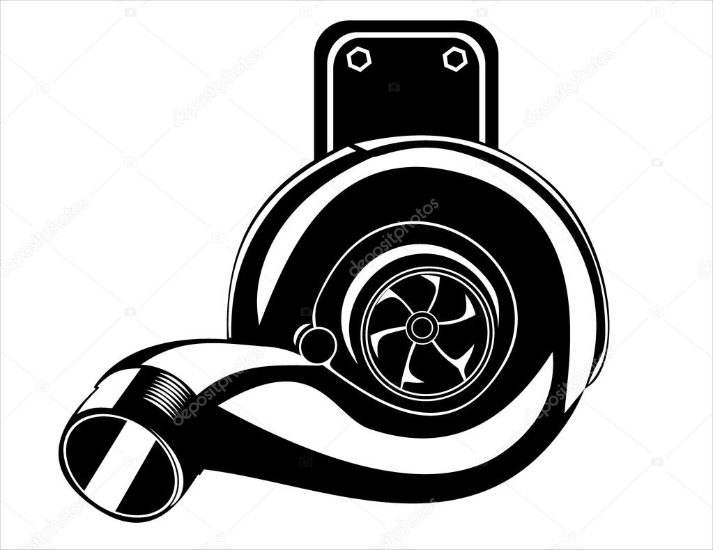
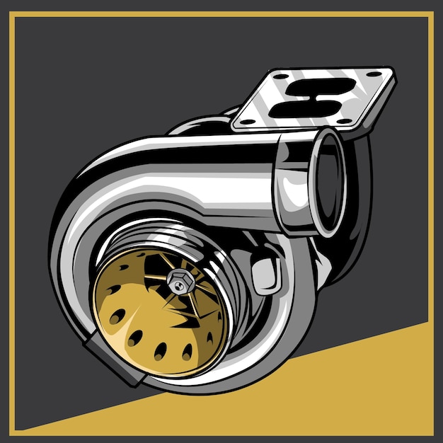
Turbocharger Drawing
Turbocharger Drawing - At the most basic level, a turbocharger consists of just three major components: Exhaust gases drive the turbine, which in turn forces more air into the engine, enhancing power and efficiency. The components that make up a typical turbocharger system are: Web let us first look at the schematic below: Turbocharger uses the exhaust gases of the engine itself, to rotate the turbine which in turn moves the compressor. 1 compressor inlet 2 compressor discharge 3 charge air cooler (cac) 4 intake valve 5 exhaust valve 6 turbine inlet 7 turbine discharge. Where can i your basic turbocharger drawings? A turbocharger is basically a combination of a compressor and a turbine, both mounted on a common shaft. How a turbo system is made up. Turbo atc.png 1,200 × 1,600; Cutaway diagrams of turbochargers (3 f) cutaway models of turbochargers (21 f) media in category cutaways of turbochargers the following 2 files are in this category, out of 2 total. We hope you learn something, as there is much misconception about draw through. Web to understand how a turbocharger works, it’s helpful to refer to a schematic diagram. A turbocharger diagram illustrates a key component of internal combustion engines. The components that make up a typical turcharger system are: Let us first look at the schematic below: Find out how to download this material. Telegram bot for searching materials. 319k views 10 years ago. A turbocharger is basically a combination of a compressor and a turbine, both mounted on a common shaft. The main components of a turbocharger include the compressor, turbine, and wastegate. 1 compressor inlet 2 compressor discharge 3 charge air cooler (cac) 4 intake valve 5 exhaust valve 6 turbine inlet 7 turbine discharge. A turbocharger. The 1988 toyota supra turbo mk 3. Web the turbocharger system converts exhaust gases into centrifugal force by flowing the exhaust through the turbine housing, forcing the turbine wheel into motion. Web so how does a turbocharger get more air into the engine? We hope you learn something, as there is much misconception about draw through. You will notice on. It represents the turbocharger parts common to all types of turbochargers. The components that make up a typical turbocharger system are: The turbine, the compressor, and the bearing system that supports the turbine shaft,. Web turbocharging is the right method to increase the intake air density. This is called the chra (center hub rotating assembly). We hope you learn something, as there is much misconception about draw through. The components that make up a typical turcharger system are: In this episode, we explain the basics of draw through turbocharging. Web let us first look at the schematic below: The 1988 toyota supra turbo mk 3. This category has the following 2 subcategories, out of 2 total. The components that make up a typical turbocharger system are: Buckle up, because we’re taking you on a ride to draw one of the most iconic sports cars of the ’80s: Web turbocharging is the right method to increase the intake air density. Where can i your basic turbocharger. Telegram bot for searching materials. Web browse 390+ turbo drawing stock photos and images available, or start a new search to explore more stock photos and images. Ready to hit the gas on your artistic skills? Web the turbocharger system converts exhaust gases into centrifugal force by flowing the exhaust through the turbine housing, forcing the turbine wheel into motion.. The components that make up a typical turbocharger system are: A turbocharger is basically a combination of a compressor and a turbine, both mounted on a common shaft. Let us first look at the schematic below: In this episode, we explain the basics of draw through turbocharging. Web how to draw a 1988 toyota supra turbo mk 3. Vnt vanes open.jpg 1,341 ×. Web turbocharging is the right method to increase the intake air density. Web so how does a turbocharger get more air into the engine? In this episode, we explain the basics of draw through turbocharging. This is called the chra (center hub rotating assembly). How a turbo system is made up. Cutaway diagrams of turbochargers (3 f) cutaway models of turbochargers (21 f) media in category cutaways of turbochargers the following 2 files are in this category, out of 2 total. Subscribe to receive an information about new materials: 319k views 10 years ago. Web turbocharging is the right method to increase the intake air density. Turbo atc.png 1,200 × 1,600; We hope you learn something, as there is much misconception about draw through. Exhaust gases drive the turbine, which in turn forces more air into the engine, enhancing power and efficiency. You will notice on the turbocharger diagram the terms inducer and exducer. Web the turbocharger system converts exhaust gases into centrifugal force by flowing the exhaust through the turbine housing, forcing the turbine wheel into motion. It requires additional work on the air intake side, on top of the pumping work of a atmospheric (naturally aspirated) engine, in order to force extra air mass in the cylinders. Web turbocharger (design description) russian. Join the grabcad community today to gain access and download! Telegram bot for searching materials. Find out how to download this material. 1 compressor inlet 2 compressor discharge 3 charge air cooler (cac) 4 intake valve 5 exhaust valve 6 turbine inlet 7 turbine discharge.
Turbocharger Vector Premium
![]()
Turbo Charger Icon in Color Drawing Stock Vector Illustration of

Turbo Drawing at Explore collection of Turbo Drawing

3D View of Turbocharger Download Scientific Diagram

Turbocharger sketch Turbocharger isolated on a white background
![]()
Turbine from automobile engine. Line illustration of car motor
![]()
Turbocharger linear icon. Thin line illustration. Colloquially turbo

Vector illustration of turbocharger. 539145 Vector Art at Vecteezy

Premium Vector Turbo illustration isolated

Free Turbocharger Watercolor Vector 130532 Vector Art at Vecteezy
At The Most Basic Level, A Turbocharger Consists Of Just Three Major Components:
A Turbocharger Diagram Illustrates A Key Component Of Internal Combustion Engines.
Web Let Us First Look At The Schematic Below:
The Components That Make Up A Typical Turbocharger System Are:
Related Post: