Tolerances Engineering Drawing
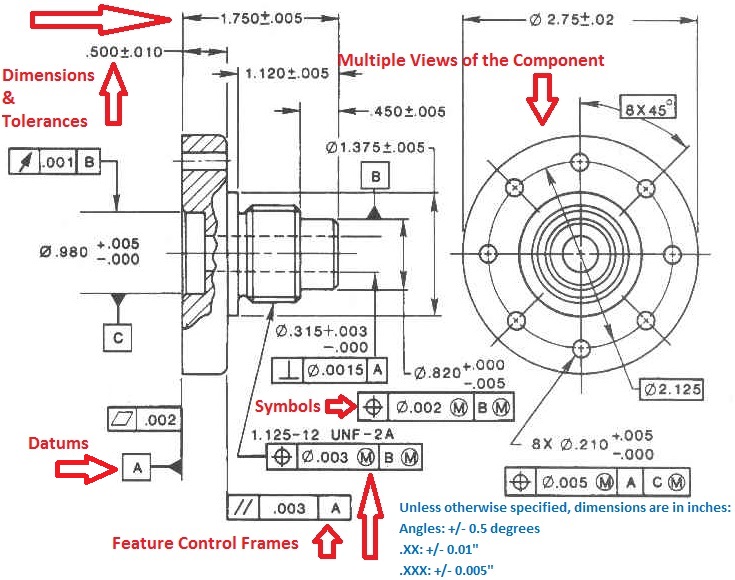
Tolerances Engineering Drawing - Web technical drawings often include notations such as “50 g6” or “17.5 h11/g8” to specify tolerances. I discuss tolerances on engineering drawings. Because it is impossible to make everything to an exact size, tolerances are used on production drawings to control the parts. And the minimum value is called the minimum dimension. Plus and minus dimensioning is the allowable positive and negative variance from the dimension specified. If you take a look at an engineering drawing, you will notice that there are always limits, or tolerances, placed on a dimension. The y14.5 standard is considered the authoritative guideline for the design language of geometric dimensioning and tolerancing (gd&t.) Drawing border exerpt featuring a general tolerancing scheme. Web by brandon john on august 3, 2021. These default tolerances would be established for ease of manufacturing. When a part is designed, the cad model is designed exactly how we want the part to be. The three main categories are: Entry of the tolerances on the drawing. Scope of the applying tolerances. Dimension tolerance is the amount of variation allowed in a size. Web tolerance is the total amount a dimension may vary and is the difference between the upper (maximum) and lower (minimum) limits. Why does the designer do this? Gd&t, short for geometric dimensioning and tolerancing, is a system for defining and communicating design intent and engineering tolerances that helps engineers and manufacturers optimally control variations in manufacturing processes. Limitations of. Limitations of tolerancing before gd&t. Web an engineering drawing may include general tolerances in the form of a table or just a little note somewhere on the drawing (e.g. This is just one example for linear tolerances for a 100 mm value. It is designed as a perfect part. Web in engineering, we have to define the tolerances of parts. If you take a look at an engineering drawing, you will notice that there are always limits, or tolerances, placed on a dimension. The default tolerances are trip wires to detect a process that is grossly malfunctioning. It’s important to keep tolerances on engineering drawings in perspective — tolerances for a given part may not be visible to the naked. Concentricity is a very complex feature because it relies on measurements from derived median points as opposed to a surface or feature’s axis. We can choose the fits according to the necessities and working conditions. Explain how to select the datum reference frames properly calculate the position and profile tolerances. Web geometric dimensioning and tolerancing is a set of rules. Tolerance is the amount a particular dimension is allowed to vary. Concentricity is a very complex feature because it relies on measurements from derived median points as opposed to a surface or feature’s axis. Web technical drawings often include notations such as “50 g6” or “17.5 h11/g8” to specify tolerances. Classification and symbols of geometric tolerance characteristics. It’s the basics. Web geometric dimensioning and tolerancing is a set of rules and gd&t symbols used on a drawing to communicate the intent of a design, focusing on the function of the part. 7.5k views 2 years ago. The default tolerances are trip wires to detect a process that is grossly malfunctioning. If you take a look at an engineering drawing, you. Web in engineering, we have to define the tolerances of parts to ensure a long lifespan and proper working of a machine. Tolerances are the ‘t’ in gd&t and are the allowable amount of variation for a physical dimension. Web geometric dimensioning and tolerancing is a set of rules and gd&t symbols used on a drawing to communicate the intent. When a part is designed, the cad model is designed exactly how we want the part to be. Web by brandon john on august 3, 2021. Dimension tolerance is the amount of variation allowed in a size. Entry of the tolerances on the drawing. Web in engineering, we have to define the tolerances of parts to ensure a long lifespan. These tolerances are applicable in different conditions such as chamfer heights, linear dimensions, external radius, angular dimensions, etc. Why would a designer set a tolerance, and why would they choose a tighter or looser tolerance for. It’s the basics of engineering tolerance. Entry of fit tolerances on the engineering drawing. Web geometric dimensioning and tolerancing is a set of rules. Web in engineering, we have to define the tolerances of parts to ensure a long lifespan and proper working of a machine. Currently, we have 16 symbols for geometric tolerances, which are categorized according to the tolerance they specify. Drawing border exerpt featuring a general tolerancing scheme. Why would a designer set a tolerance, and why would they choose a tighter or looser tolerance for. Engineering tolerance is the permissible limit or limits of variation in: Plus and minus dimensioning is the allowable positive and negative variance from the dimension specified. Gd&t, short for geometric dimensioning and tolerancing, is a system for defining and communicating design intent and engineering tolerances that helps engineers and manufacturers optimally control variations in manufacturing processes. Interpret and explain the application of geometric symbols on drawings. Why does the designer do this? The maximum allowable value is called the maximum dimension. Tolerances are the ‘t’ in gd&t and are the allowable amount of variation for a physical dimension. Web engineering tolerances include dimension tolerance, shape tolerance, and position tolerance. If you take a look at an engineering drawing, you will notice that there are always limits, or tolerances, placed on a dimension. The default tolerances are trip wires to detect a process that is grossly malfunctioning. The y14.5 standard is considered the authoritative guideline for the design language of geometric dimensioning and tolerancing (gd&t.) Dimension tolerance is the amount of variation allowed in a size.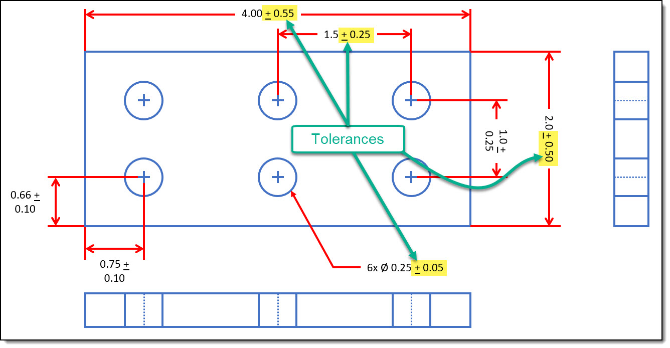
Engineering Drawings & GD&T For the Quality Engineer
Types Of Tolerance In Engineering Drawing at GetDrawings Free download
Fit and Dimensional Tolerances Mechanical Engineering Drawing

GD&T 101 An Introduction to Geometric Dimensioning and Tolerancing
Types Of Tolerance In Engineering Drawing at GetDrawings Free download
Engineering Tolerances Design Learning Objects

Tolerances A Brief Introduction EngineeringClicks

Drawing with tolerances Technical drawing, Learn autocad, Geometric

Examples of Determining the Tolerance on an Engineering Drawing? ED

Technical Drawing Tolerances
Our Online Calculator Streamlines This Process And Provides A Detailed Final Result Immediately.
Entry Of The Tolerances On The Drawing.
It’s The Basics Of Engineering Tolerance.
These Tolerances Are Applicable In Different Conditions Such As Chamfer Heights, Linear Dimensions, External Radius, Angular Dimensions, Etc.
Related Post:
