Technical Drawing Symbols
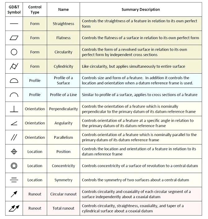
Technical Drawing Symbols - Symbols take less time to apply on a drawing than would be required to state the same requirements with words. These symbols are placed in the first compartment of a feature control frame and define the geometry characteristic of the feature that is to be controlled. But they do not provide the information that technical drawings give you. Web engineering drawing abbreviations and symbols are used to communicate and detail the characteristics of an engineering drawing. The symbols also require considerably less space. Web iso 6433:1981, technical drawings ? Gd&t is such a standard for assembly design and production. This list includes abbreviations common to the vocabulary of people who work with engineering drawings in the manufacture and inspection of parts and assemblies. The characteristics are grouped into four types of tolerance: The need for precise communication in the preparation of a functional document distinguishes technical drawing from. Web tolerances are specified, and each symbol has a clearly defined meaning. The characteristics are grouped into four types of tolerance: Equivalent symbol and note 1.2 the symbols are presented in two groups for easier. Web engineering drawing abbreviations are a set of standardized symbols and abbreviations used on engineering drawings to represent common terms and phrases. Web the base. Web many of the symbols and principles of technical drawing are codified in an international standard called iso 128. If you’re studying engineering and need a reference sheet for these drafting symbols, you’ve come to the right place. These symbols usually represent measurements, dimensions, angles, and other specifications related to the object being drawn. In addition, knowledge of the software. In addition, knowledge of the software used to create the drawings is required. Web once you know what type of drawing you're looking at, take some time to familiarize yourself with the common symbols used in technical drawings. These engineering or technical drawings serve a number of different purposes. In order to communicate accurately in any written language, the writer. Web there are 12 geometric tolerancing characteristics with the corresponding symbols shown. The symbols and abbreviations represent various components, processes, and measurements used in engineering design. You can also check out the gd&t symbols and terms on our site. Web the following is a short list of symbols that normally appear on a technical drawing and need understanding. Web geometric. The symbols also require considerably less space. We offer you our tips which we believe are useful for dispelling uncertainty by comparing the symbol with its graphic representation. You can also check out the gd&t symbols and terms on our site. Edges of undefined shape ? General and types of drawings [11] iso 13715:2000, technical drawings ? Web once you know what type of drawing you're looking at, take some time to familiarize yourself with the common symbols used in technical drawings. These engineering or technical drawings serve a number of different purposes. Symbols take less time to apply on a drawing than would be required to state the same requirements with words. Terms relating to technical. This list includes abbreviations common to the vocabulary of people who work with engineering drawings in the manufacture and inspection of parts and assemblies. The following tables show how to construct the symbols. The characteristics are grouped into four types of tolerance: Web the following is a short list of symbols that normally appear on a technical drawing and need. Edges of undefined shape ? If you’re studying engineering and need a reference sheet for these drafting symbols, you’ve come to the right place. The following tables show how to construct the symbols. The characteristics are grouped into four types of tolerance: Form, orientation, location, and runout. Web technical drawings & gd&t. If you’re studying engineering and need a reference sheet for these drafting symbols, you’ve come to the right place. The need for precise communication in the preparation of a functional document distinguishes technical drawing from. Symbols take less time to apply on a drawing than would be required to state the same requirements with words.. This list includes abbreviations common to the vocabulary of people who work with engineering drawings in the manufacture and inspection of parts and assemblies. This article provides an overview of technical drawings. The need for precise communication in the preparation of a functional document distinguishes technical drawing from. These symbols are placed in the first compartment of a feature control. General and types of drawings [11] iso 13715:2000, technical drawings ? Web an engineering (or technical) drawing is a graphical representation of a part, assembly, system, or structure and it can be produced using freehand, mechanical tools, or computer methods. But they do not provide the information that technical drawings give you. Web to use technical drawings effectively, specialist knowledge is required to understand the symbols, rules, and standards used. Web there are 12 geometric tolerancing characteristics with the corresponding symbols shown. Web geometric dimensioning and tolerancing, or gd&t for short, is a language of symbols used to communicate information on technical drawings. Web tolerances are specified, and each symbol has a clearly defined meaning. Symbols take less time to apply on a drawing than would be required to state the same requirements with words. Web many of the symbols and principles of technical drawing are codified in an international standard called iso 128. The symbols and abbreviations represent various components, processes, and measurements used in engineering design. In this article, we’ll introduce the gd&t terms and definitions, as well as the chart of gd&t symbols. “learning gd&t from scratch,” provided by keyence, walks you through the basics of geometric dimensioning and tolerancing, datums, and measurements by coordinate measuring. Equivalent symbol and note 1.2 the symbols are presented in two groups for easier. Form, orientation, location, and runout. In order to communicate accurately in any written language, the writer and the reader must share the same understanding of the symbols and structure of that language. Manufacturing technical drawings are not replacements for 3d cads, which are excellent representations of products.
Engineering Drawing Symbols And Their Meanings Pdf at PaintingValley

Mechanical Engineering Drawing Symbols Pdf Free Download at

Engineering Drawing Symbols And Their Meanings Pdf at PaintingValley

ANSI Standard JSTD710 Architectural Drawing Symbols Bedrock Learning
Civil Engineering Drawing Symbols And Their Meanings at PaintingValley

Mechanical Engineering Drawing Symbols Pdf Free Download at

Civil Engineering Drawing Symbols And Their Meanings at PaintingValley

Engineering Drawing Symbols And Their Meanings Pdf at PaintingValley

ANSI Standard JSTD710 Architectural Drawing Symbols Bedrock Learning
Engineering Drawing Symbols And Their Meanings Pdf at PaintingValley
Web This Page Explains The 16 Symbols Used In Gd&T, And The Classification Thereof.
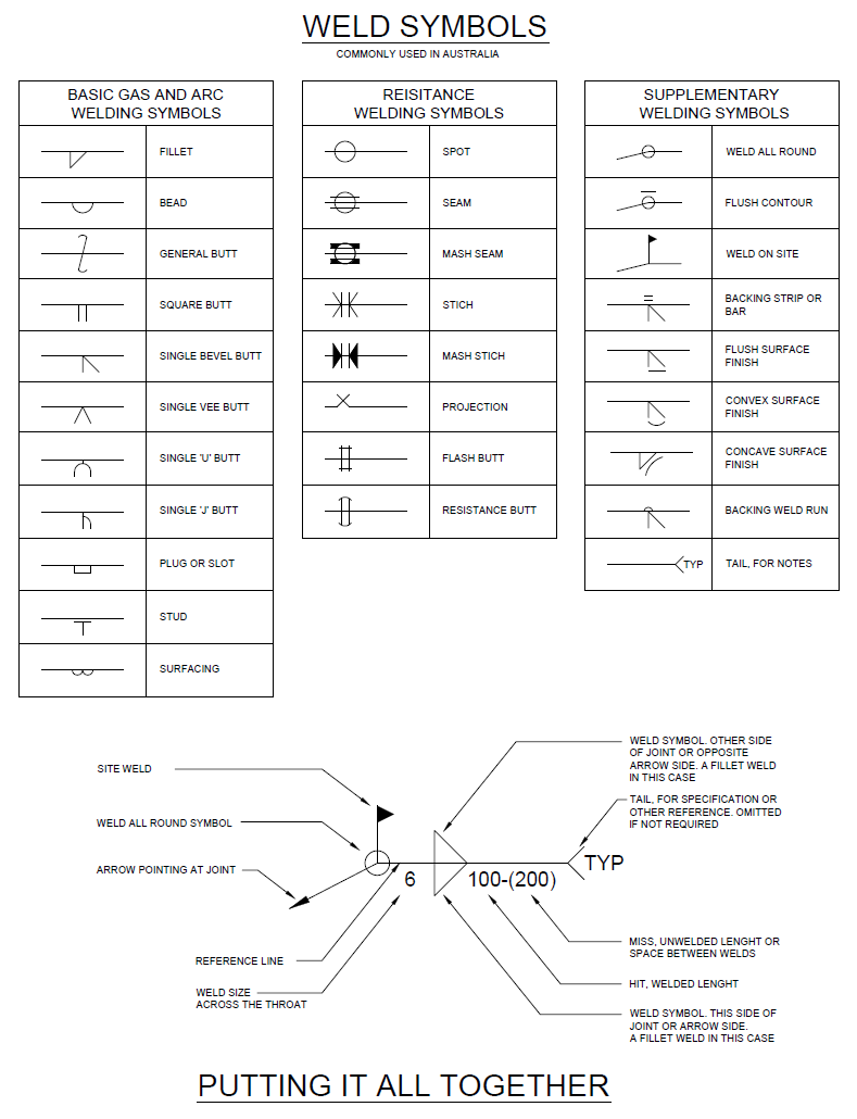
Web Engineering Drawing Abbreviations And Symbols Are Used To Communicate And Detail The Characteristics Of An Engineering Drawing.
Edges Of Undefined Shape ?
In The Last Chapter ( Design Inputs & Reviews ), We Covered The Three Phases Of Product Design Which Often Result In The Creation Of Detailed Engineering Drawings Associated With Your New Product.
Related Post: