Section Line In Engineering Drawing
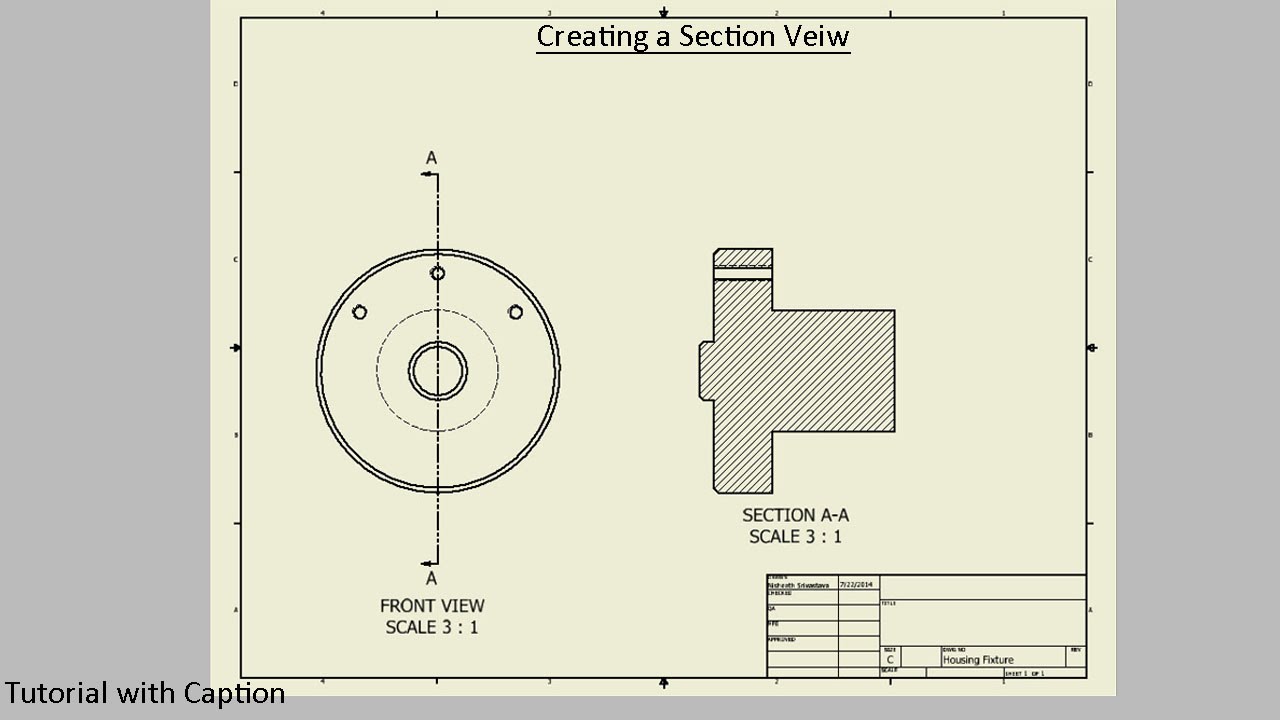
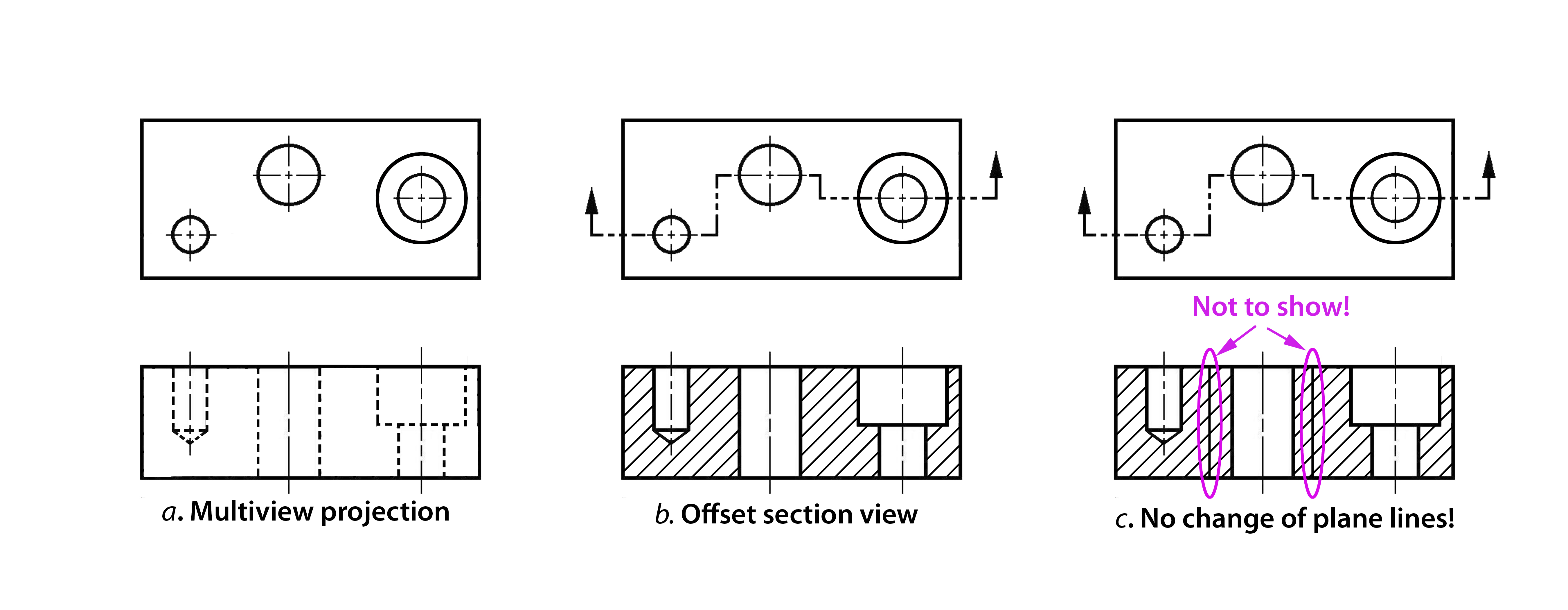
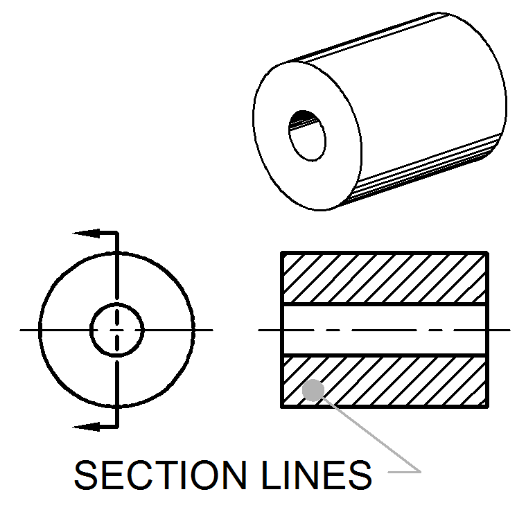
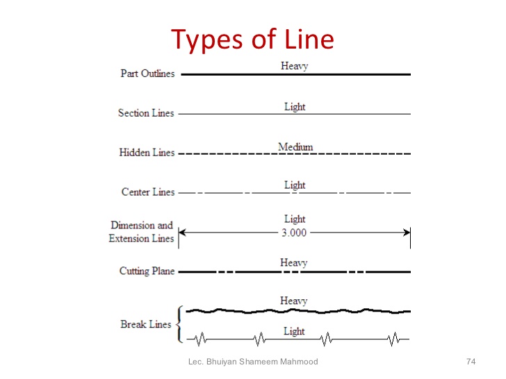
Section Line In Engineering Drawing - Engineering drawings use standardised language and symbols. A full section view is where the entire part or assembly is cut on a single plane. Arrows indicate the direction of view. The purpose is to convey all the information necessary for manufacturing a product or a part. Section lines are thin lines that fill the cut area of the object and show the direction. Web there are 12 types of lines usually used in engineering drawing. A section lined area is always completely bounded by a visible outline. Section lines are drawn as thin (.35 mm) black lines, using an h or 2h pencil. Web section lines are generally drawn at a 45° angle. They are 0.6 mm thick. Web in short, a section drawing is a view that depicts a vertical plane cut through a portion of the project. The main elements of the section view are: The purpose is to convey all the information necessary for manufacturing a product or a part. Web section lines are generally drawn at a 45° angle. It is frequently necessary for. Section lines shown in opposite directions indicate a. Web this manufacturer’s drawing, using both full and half section, illustrates the advantages of sectional views. Web section lines are generally drawn at a 45° angle. Web sectional drawings are multiview technical drawings that contain special views of a part or parts, a view that reveal interior features. This identifies the orientation. Web section drawing in engineering. An engineering drawing is a subcategory of technical drawings. They are 0.6 mm thick. Web you should not dimension to hidden lines: The section lines in all areas should be parallel. The purpose is to convey all the information necessary for manufacturing a product or a part. Web the picture below shows how our object would be represented in the engineering drawing. It is frequently necessary for manufacturers to know what the inside of such objects looks like. This identifies the orientation of the view that is created also. They are. Arrows indicate the direction of view. Engineering objects often have complex inner structures, such as the inside of a jet engine. The different line directions indicate different parts and materials used in the assembly of this valve. Size dimensions indicate the size of basic shapes like arcs, prisms, cylinders, and holes. Web sectional drawings are multiview technical drawings that contain. Web you should not dimension to hidden lines: Section lines are drawn as thin (.35 mm) black lines, using an h or 2h pencil. They are dark and thick lines of any engineering design drawing. Do not confuse section lines with cutting plane lines. Web the general purpose or cast iron section line is drawn at a 450 angle and. A circular arc is dimensioned by its. The purpose is to convey all the information necessary for manufacturing a product or a part. A section lined area is always completely bounded by a visible outline. Web the picture below shows how our object would be represented in the engineering drawing. Phantom lines are used to represent a movable feature in. The different line directions indicate different parts and materials used in the assembly of this valve. On a separate sheet of paper, complete the section view. Web this manufacturer’s drawing, using both full and half section, illustrates the advantages of sectional views. A section lined area is always completely bounded by a visible outline. Web the line that indicates the. Phantom lines are used to represent a movable feature in its different positions. Section line, section reference arrow, section reference letters, hatch. Do not confuse section lines with cutting plane lines. i have described each type of line briefly. Web section drawing in engineering. Web the most general form of section lining consists of parallel thin lines drawn at an angle. It is frequently necessary for manufacturers to know what the inside of such objects looks like. Engineering objects often have complex inner structures, such as the inside of a jet engine. Use a section view to make hidden lines visible, or use a. They are dark and thick lines of any engineering design drawing. Web the diagonal lines on the section drawing are used to indicate the area that has been theoretically cut. Visible lines are used to represent features that can be seen in the current view. The main elements of the section view are: They are fine, dark lines. Do not confuse section lines with cutting plane lines. A full section view is where the entire part or assembly is cut on a single plane. Web lines in engineering drawing are more than just strokes on paper; Web to indicate a section view in an engineering drawing, you need to use section lines and symbols. Web section drawing in engineering. Section lines are drawn as thin (.35 mm) black lines, using an h or 2h pencil. The purpose is to convey all the information necessary for manufacturing a product or a part. The section lines in all areas should be parallel. Web the line that indicates the plane where the cut is made is called the section line. These types of lines also known as object lines. Sometimes a note tells the reader in which zone(s) of the drawing to find the view or section.
Engineering Drawing Tutorials / Orthographic Drawing with Vertical
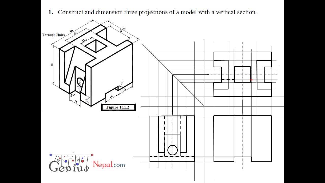
Engineering Drawing Tutorials/Orthographic and sectional views ( T 11.2

SECTION DRAWINGS BRANDON OWENS' PORTFOLIO
Sectional View Engineering Drawing Exercises at GetDrawings Free download
Sectioning Technique Engineering Design McGill University
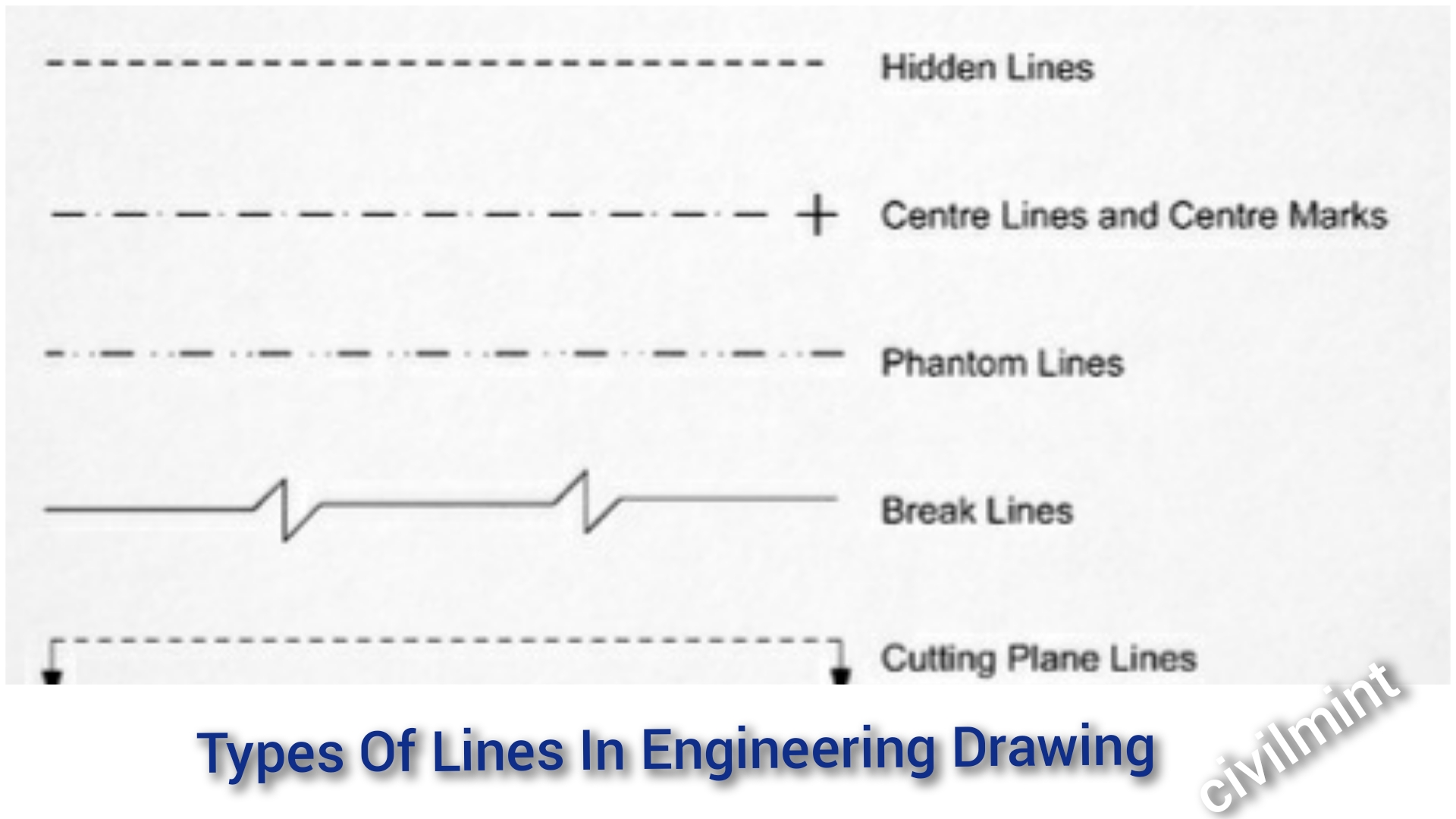
Types Of Lines In Engineering Drawing
Section Lines ToolNotes
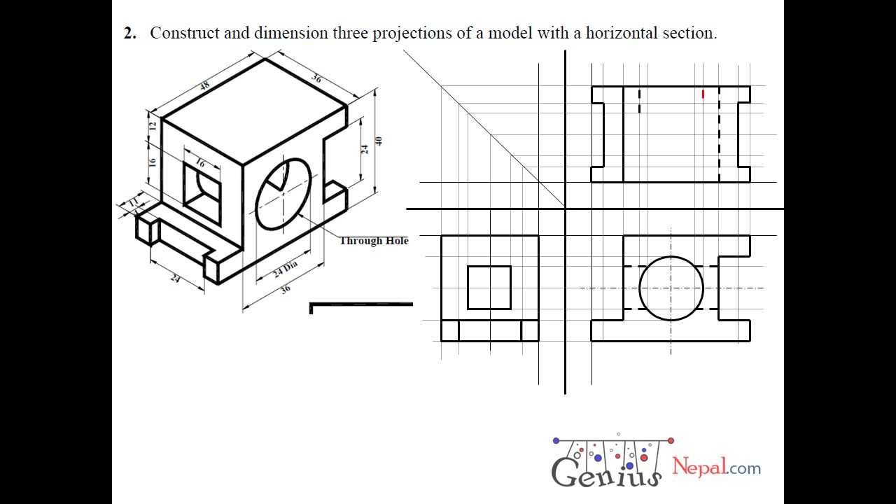
Engineering Drawing Tutorials/Orthographic and sectional views ( T 11.3
Engineering Drawing 8 Tips to Improve Engineering Drawing Skills

Sectional View in Engineering Drawing YouTube
Web Section Lines Are Used To Show The Cut Surfaces Of An Object In Section Views.
They Convey Critical Information, Dimensions, And Details That Guide The Construction Of Complex Structures, Machinery, And Systems.
They Are 0.6 Mm Thick.
Use A Section View To Make Hidden Lines Visible, Or Use A Hole Callout If Possible.
Related Post: