Relay Schematic Drawing
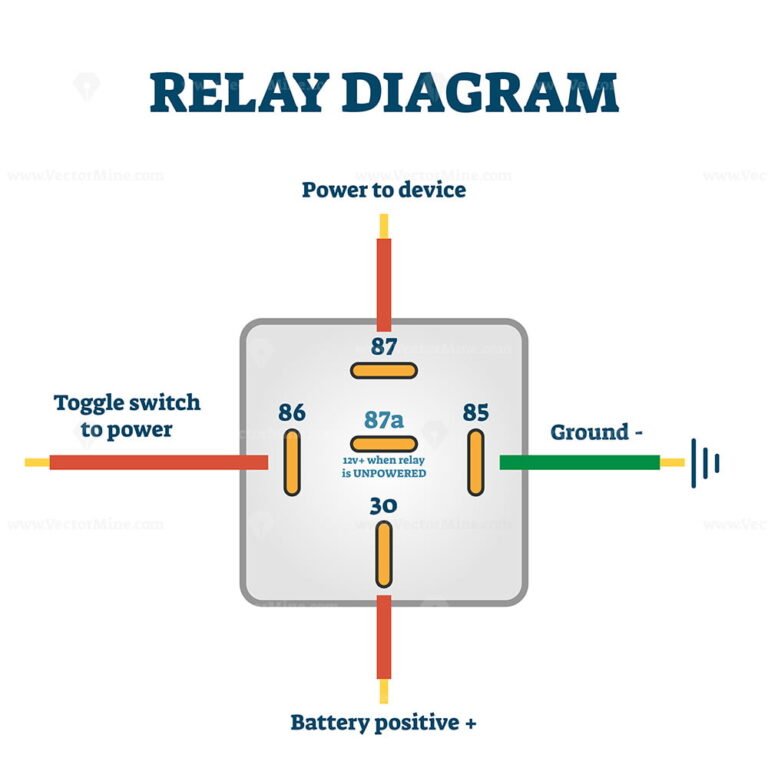
Relay Schematic Drawing - Web protection & control relaying schematics. Web a very common form of schematic diagram showing the interconnection of relays to perform these functions is called a ladder diagram. What are iso relays used for? This technical article explains the ac/dc schematic representation of the protection and control systems used on power networks. Web however a relay switch circuit can be used to control motors, heaters, lamps or ac circuits which themselves can draw a lot more electrical voltage, current and therefore power. Web electrical drawings, schematics, and wiring diagrams: A very common form of schematic diagram showing the interconnection of relays to perform these functions is called a ladder diagram. The electromagnet becomes connected to the power source through the contacts to the load and a control switch. Web a relay switch circuit diagram is a schematic representation of the electrical connections and components used to control an electrical circuit using a relay. Different voltage and current can be ‘interposed’ to provide safety, efficiency, and compatibility between systems. Web when wiring a 12 volt relay, it is important to follow the schematic diagram provided by the manufacturer. Web protection & control relaying schematics. A relay is an electrically operated switch. In a “ladder” diagram, the two poles of the power source are drawn as vertical rails of a ladder, with horizontal “rungs” showing the switch contacts, relay contacts,. Web electrical drawings, schematics, and wiring diagrams: Web we will introduce the basic knowledge of relay and teach you how to draw a customized relay wiring diagram. A control coil surrounds the iron core. A simple explanation of latching relays. Web basic construction of relay: A simple explanation of latching relays. The electromagnet becomes connected to the power source through the contacts to the load and a control switch. Web learn what a latching relay is, how a latching relay works, and a latching relay circuit diagram. Relays are electromagnetic devices that can be used to control one circuit using another circuit. In a “ladder”. Web the figure above shows the inner sections diagram of a relay. Web learn what a latching relay is, how a latching relay works, and a latching relay circuit diagram. They commonly use an electromagnet (coil) to operate their internal mechanical switching mechanism (contacts). Web a relay switch circuit diagram is a schematic representation of the electrical connections and components. They commonly use an electromagnet (coil) to operate their internal mechanical switching mechanism (contacts). Web by clint byrd | december 16, 2021. C is the common terminal; Web however a relay switch circuit can be used to control motors, heaters, lamps or ac circuits which themselves can draw a lot more electrical voltage, current and therefore power. Web 4 &. Web protection & control relaying schematics. No is the normally open contact; Web when wiring a 12 volt relay, it is important to follow the schematic diagram provided by the manufacturer. What is a relay and how does it work? The electromagnet becomes connected to the power source through the contacts to the load and a control switch. Among other things, we can distinguish: Also known as impulses, bistable, keep, or stay relay. Web examples of just some of the more common diagrams used for electrical relay contact types to identify relays in circuit or schematic diagrams is given below but there are many more possible configurations. C is the common terminal; It is used to programmatically control. What is a relay and how does it work? January 15, 2024 by david peterson. The electromagnet starts energizing when the current flows through the control coil then intensifies the magnetic field. A relay is an electrically operated switch. Web schematic symbols for relays. Web we will introduce the basic knowledge of relay and teach you how to draw a customized relay wiring diagram. This technical article explains the ac/dc schematic representation of the protection and control systems used on power networks. A relay logic circuit is a schematic diagram which shows various components, their connections, inputs as well as outputs in a particular. January 15, 2024 by david peterson. C is the common terminal; Web when wiring a 12 volt relay, it is important to follow the schematic diagram provided by the manufacturer. A control coil surrounds the iron core. This includes ac schematics and dc schematics and diagrams that prominently feature relaying. C is the common terminal; The electromagnet becomes connected to the power source through the contacts to the load and a control switch. A relay logic circuit is a schematic diagram which shows various components, their connections, inputs as well as outputs in a particular fashion. This diagram shows the connections and components required to properly control the relay. Spst relay (single pole single throw) which contains 4 pin Electromechanical relays may be connected together to perform logic and control functions, acting as logic elements much like digital gates (and, or, etc.). The number and type of contacts depends on the model of the relay. In order to realize the function of the relay, you have to know its basic construction of it. Web 4 & 5 pin relay schematics. Web by clint byrd | december 16, 2021. This technical article explains the ac/dc schematic representation of the protection and control systems used on power networks. In relay logic circuits, the contacts no and nc are used to indicate normally open or normally close relay circuit. Web protection & control relaying schematics. Web learn what a latching relay is, how a latching relay works, and a latching relay circuit diagram. They commonly use an electromagnet (coil) to operate their internal mechanical switching mechanism (contacts). Relays are used in many different projects, from controlling motors and lights to powering up a circuit to doing something as seemingly mundane as switching a power strip on or off.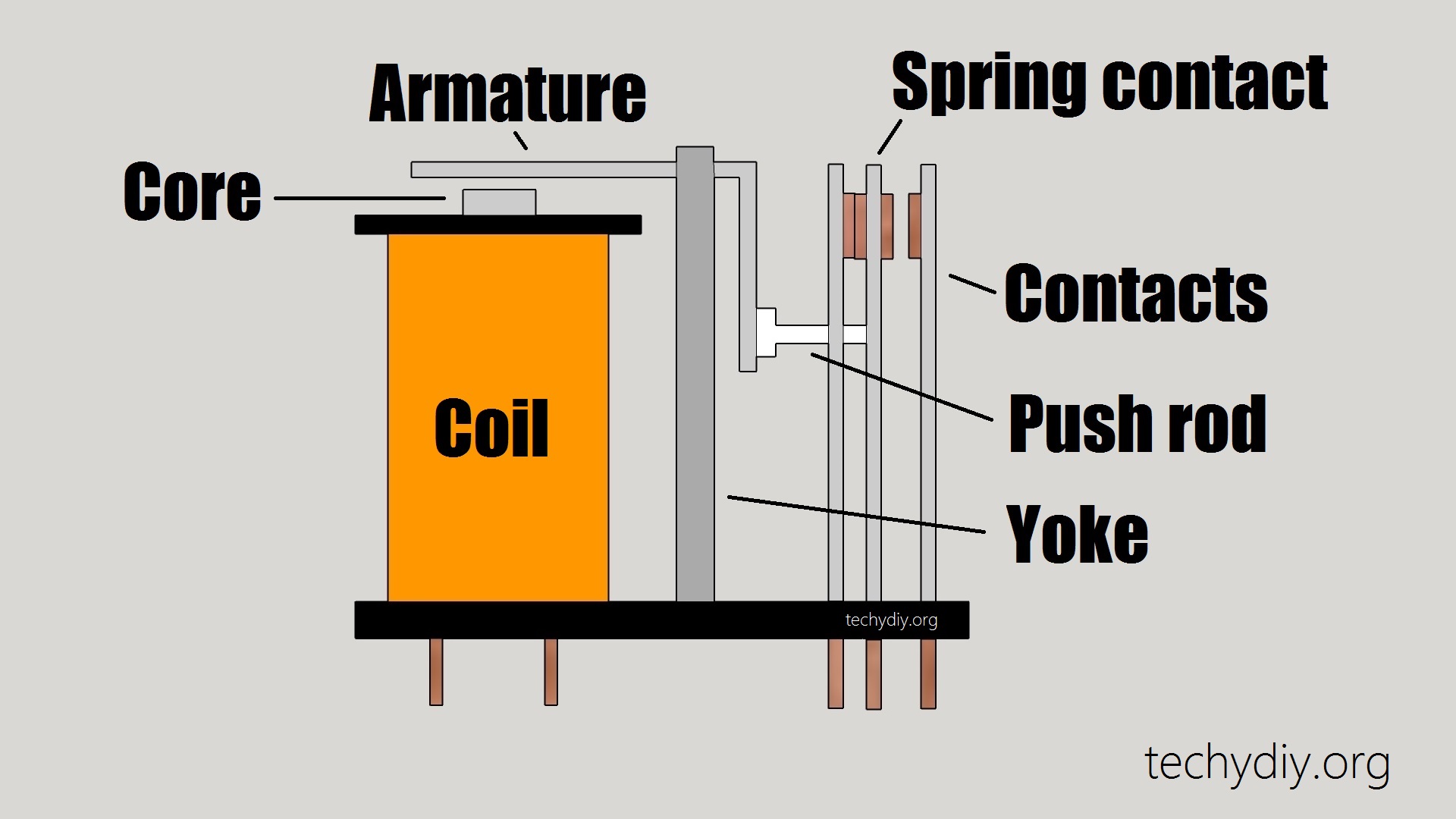
How does an Electric Relay work? Techydiy

How To Read Relay Schematic
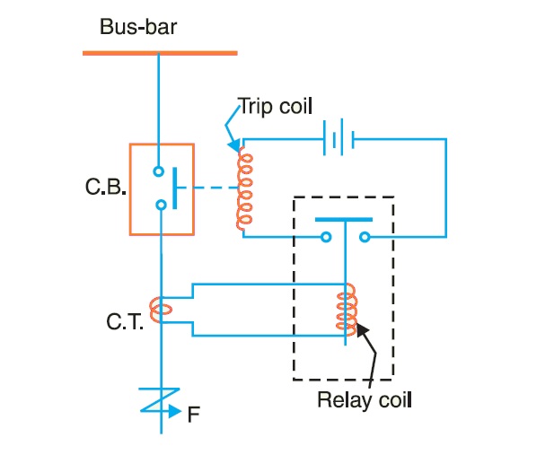
How Protective Relays Work? StudyElectrical Online Electrical

5 Pin Relay Wiring Diagram Use Of Relay
FREE Relay switch example diagram drawing, vector illustration scheme

Electrical Schematic Symbol Relays CAD Block And Typical Drawing
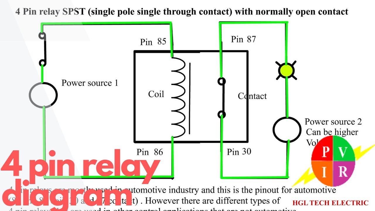
4 pin relay diagram. 4 pin relay wiring. 4 pin relay animation. 4 pin

6 Pin Relay Schematic

Relay Wiring Diagram and Function Explained ETechnoG
Overload Relay Schematic Symbol
Relays Are Electromagnetic Devices That Can Be Used To Control One Circuit Using Another Circuit.
No Is The Normally Open Contact;
Web Electrical Drawings, Schematics, And Wiring Diagrams:
Web Schematic Symbols For Relays.
Related Post: