Piping And Instrumentation Drawing
Piping And Instrumentation Drawing - To read and understand engineering fluid diagrams and prints, usually referred to as p&ids, an individual must be familiar with the basic symbols. P&ids are foundational to the maintenance and modification of the process that it graphically represents. Web a piping and instrumentation diagram (p&id or pid) is a detailed diagram in the process industry which shows the piping and process equipment together with the instrumentation and control devices. P&ids provide key piping and instrumentation items along with their proper arrangement. Web piping & instrumentation drawings (p&ids) are important communication tools for engineers. Lacking these safety features could lead to serious. Web a p&id (also known as pefs, process engineering flow scheme) is a fundamental engineering document that serves various purposes as mentioned below. The easiest way to visualize your piping process and instrumentation by using our professional piping design software. It serves as a basic document for operation, control, and shutdown schemes. It shows the equipment used in the process, and all of the signals required to measure and control the process. The easiest way to visualize your piping process and instrumentation by using our professional piping design software. This information is displayed in the areas surrounding the graphic portion of the drawing. Available for windows, mac and linux. Through a p&id, you can get the following information: Web a piping and instrumentation diagram, or p&id, shows the piping and related components. Web a p&id (also known as pefs, process engineering flow scheme) is a fundamental engineering document that serves various purposes as mentioned below. Interpreting piping and instrumentation diagrams. A p&id uses simple graphics to represent complex processes and convey the flow of material through a process. These symbols can represent actuators, sensors, and controllers and may be apparent in most,. P&id is more complex than pfd and includes lots of details. Define the scope of the system before drawing a p&id. Start doing things in edrawmax online. It's a simple way of using lines and symbols to tell the story of how liquids and gases move around, and how machines control them. An essential guide for developing and interpreting piping. Piping and instrumentation diagrams (p&id) are standardized in many ways, and there are some fundamental safety features that are absolute requirements for all p&ids. In other words it is also called a process and instrumentation diagram or simply a p&i diagram or drawing. To be effective in the workplace, you must be able to read and interpret them. Through a. To facilitate your knowledge of piping & instrumentation drawings, professor barry m. These symbols can represent actuators, sensors, and controllers and may be. Start doing things in edrawmax online. List all the equipment in the process including pipings. Web piping and instrumentation diagrams (p&ids) use specific symbols to show the connectivity of equipment, sensors, and valves in a control system. Available for windows, mac and linux. Web a piping and instrumentation diagram (p&id) is a detailed drawing that shows the piping and instrumentation of a processing plant. Web piping and instrumentation diagrams (p&ids) use specific symbols to show the connectivity of equipment, sensors, and valves in a control system. The mechanical and electrical details of a given system or process,. Valves are used to control the direction, flow rate, and pressure of fluids. Unfortunately, many people forget these features in their designs unintentionally. In other words it is also called a process and instrumentation diagram or simply a p&i diagram or drawing. These symbols can represent actuators, sensors, and controllers and may be apparent in most, if not all, system. In other words it is also called a process and instrumentation diagram or simply a p&i diagram or drawing. Web the term p&id stands for piping and instrumentation diagram or drawing. P&ids are foundational to the maintenance and modification of the process that it graphically represents. P&ids are commonly called engineering flow drawings or mechanical flow diagrams. A link to. Web p&id is short for “piping and instrumentation diagram”. A through knowledge of the information presented in the title block, the revision block, the notes and legend, and the drawing grid is necessary before a drawing can be read. Web a p&id (also known as pefs, process engineering flow scheme) is a fundamental engineering document that serves various purposes as. Web a p&id (also known as pefs, process engineering flow scheme) is a fundamental engineering document that serves various purposes as mentioned below. A p&id uses simple graphics to represent complex processes and convey the flow of material through a process. P&ids are foundational to the maintenance and modification of the process that it graphically represents. Web a piping and. Function and purpose of p&ids. P&id is more complex than pfd and includes lots of details. This drawing is developed during the design stage of the plant and is later used to assist. It serves as a vital tool in the process industry, forming the backbone of the design phase and providing a detailed layout of the plant's process. 1/5 in the series how to interpret piping and instrumentation diagrams. It's a simple way of using lines and symbols to tell the story of how liquids and gases move around, and how machines control them. These symbols can represent actuators, sensors, and controllers and may be apparent in most, if not all, system diagrams. A through knowledge of the information presented in the title block, the revision block, the notes and legend, and the drawing grid is necessary before a drawing can be read. © 2019 john wiley & sons, inc. Through a p&id, you can get the following information: Web a p&id (also known as pefs, process engineering flow scheme) is a fundamental engineering document that serves various purposes as mentioned below. It’s most commonly used in the engineering field. A p&id uses simple graphics to represent complex processes and convey the flow of material through a process. It serves as a basic document for operation, control, and shutdown schemes. Unfortunately, many people forget these features in their designs unintentionally. Web piping and instrumentation diagrams (p&ids) use specific symbols to show the connectivity of equipment, sensors, and valves in a control system.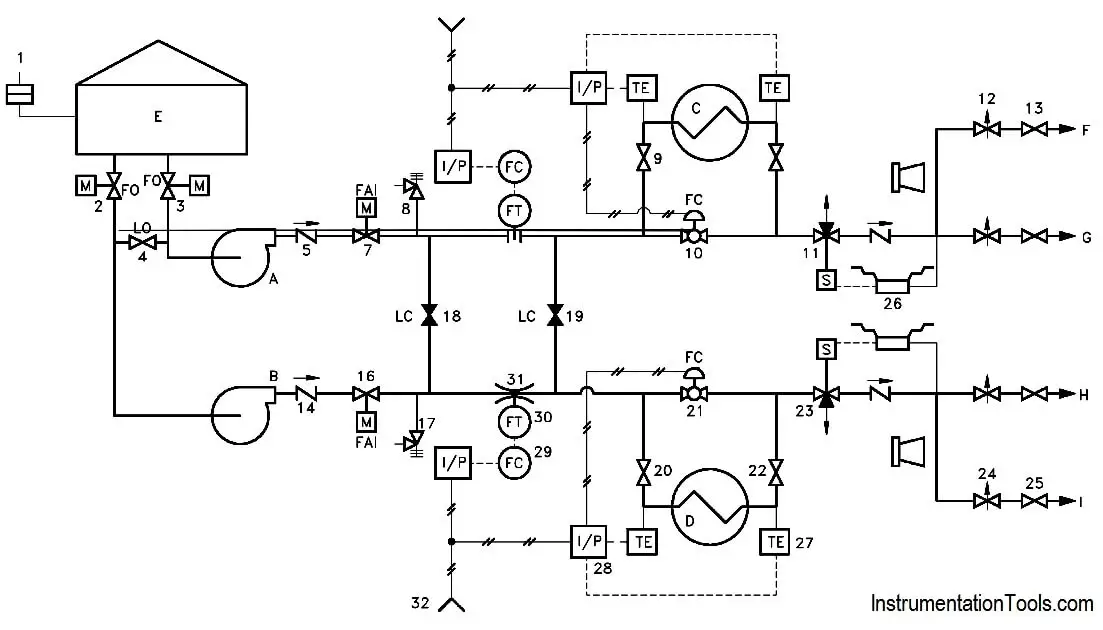
Piping and Instrumentation Documents Instrumentation Tools
![How to read a piping and instrumentation drawing? [Video] Valve Solutions](https://1.bp.blogspot.com/-GgHH1pcU0W0/WlNHvPbeyZI/AAAAAAAAAQY/NO9bREo9MDQAdPValYZ3zicXM5egYb4ygCLcBGAs/w1200-h630-p-k-no-nu/bp129.jpg)
How to read a piping and instrumentation drawing? [Video] Valve Solutions
What is Piping and Instrumentation Diagram (P&ID) ? Instrumentation Tools

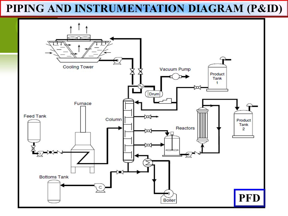
P&ID Piping and Instrument Diagrams (PID) Creative Engineers, Inc.
![[DIAGRAM] Piping And Instrumentation Diagram Lecture](https://cdn.instrumentationtools.com/wp-content/uploads/2020/01/Questions-on-Piping-and-Instrumentation-Diagrams.png)
[DIAGRAM] Piping And Instrumentation Diagram Lecture

How to Read and Interpret Piping and Instrumentation Diagrams (P&ID
Piping and Instrumentation Diagram P&ID By TheEngineeringConcepts

P & ID Diagram. How To Read P&ID Drawing Easily. Piping
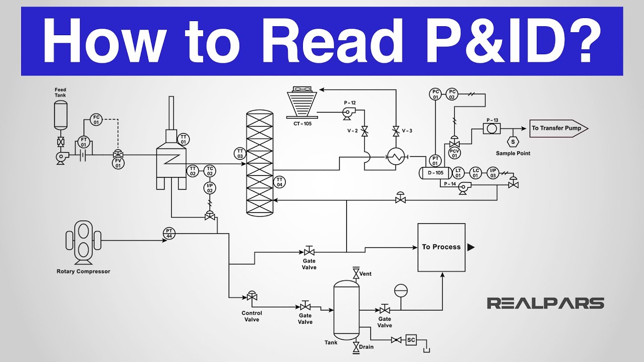
How to Read a P&ID? (Piping & Instrumentation Diagram) YouTube

Piping & Instrumentation Diagrams (P&IDs) Punchlist Zero
Define The Scope Of The System Before Drawing A P&Id.
Available For Windows, Mac And Linux.
You Will Learn How To Read P&Id And Pefs With The Help Of The Actual Plant Drawing.
A Link To Download This P&Id Is Given At The End Of The Page.
Related Post: