P Id Drawings
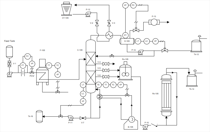
P Id Drawings - It serves as a vital tool in the process industry, forming the backbone of the design phase and providing a detailed layout of the plant's process. A diagram which shows the interconnection of process equipment and the instrumentation used to control the process. Web the p&id drawing is usually used in the process industry and engineering field. Piping & instrumentation diagram explained. If you missed the first post in the series, p&id drawings 101, please review it first. Learn what the p&id symbols mean for your manufacturing enterprise’s process, and why they are important to understand for hmi design. It serves as a blueprint that outlines the interconnection of piping, equipment, instrumentation, and controls within a process system. Building smart p&id drawings from point cloud data in a proven innovative approach for the process industry. It includes all piping, instruments, valves, and equipment the system consists of. Web a piping and instrumentation diagram (p&id) is a comprehensive schematic that illustrates the functional relationship of piping, instrumentation, and system equipment components within a process plant. A diagram which shows the interconnection of process equipment and the instrumentation used to control the process. Through a p&id, you can get the following information: The following diagrams will have more detail than in the first post. Reading real world examples | corso systems. As this diagram covers many types of diagrams as the variety in industries is vast,. The mechanical and electrical details of a given system or process, P&ids are used to develop guidelines and standards for facility operation. Web corso systems describes the basic concepts of p&id drawings so you can read and understand them in the context of process control and automation. Web a piping and instrumentation diagram (p&id) is a comprehensive schematic that illustrates. Web the p&id drawing is usually used in the process industry and engineering field. It's a simple way of using lines and symbols to tell the story of how liquids and gases move around, and how machines control them. Web p&id drawing, or piping and instrumentation diagrams, is like a special map that shows how pipes and instruments work together. P&id diagrams are made with specific and standard shapes and symbols. It is the basic training document to explain the process details to operation guys, field engineers, and maintenance professionals. It serves as a vital tool in the process industry, forming the backbone of the design phase and providing a detailed layout of the plant's process. P&id is more complex. Web how to read p&id drawing easily. It serves as a blueprint that outlines the interconnection of piping, equipment, instrumentation, and controls within a process system. It is also known as pefs (process engineering flow scheme). They are typically created by engineers who are designing a manufacturing process for a physical plant. A diagram which shows the interconnection of process. It is the basic training document to explain the process details to operation guys, field engineers, and maintenance professionals. P&id is more complex than pfd and includes lots of details. A diagram which shows the interconnection of process equipment and the instrumentation used to control the process. Every symbol contains letters and a number. Web how to read p&id drawing. Web p&id drawing, or piping and instrumentation diagrams, is like a special map that shows how pipes and instruments work together in factories and plants. It's a simple way of using lines and symbols to tell the story of how liquids and gases move around, and how machines control them. Piping and instrumentation diagrams are typically created by engineers who. Web p&id drawing, or piping and instrumentation diagrams, is like a special map that shows how pipes and instruments work together in factories and plants. Through a p&id, you can get the following information: Web the p&id drawing is usually used in the process industry and engineering field. Building smart p&id drawings from point cloud data in a proven innovative. P&id, short for piping and instrumentation diagram, is a crucial visual representation in the field of engineering. Web a piping and instrumentation diagram, also called p&id, is a diagram used to show a graphical display of a complete system. Web p&ids are a schematic illustration of the functional relationship of piping, instrumentation and system equipment components used in the field. Piping & instrumentation diagram explained. It is also known as pefs (process engineering flow scheme). They offer a detailed overview of the process flow, including equipment, valves, and instrumentation, crucial for design and operational. It is the basic training document to explain the process details to operation guys, field engineers, and maintenance professionals. They are typically created by engineers who. Every symbol contains letters and a number. These diagrams provide a map for the engineering system's design which is helpful to problem identification and solving. It serves as a vital tool in the process industry, forming the backbone of the design phase and providing a detailed layout of the plant's process. Mechanical equipment with names and numbers. Create yours using lucidchart for free when you sign up! Process piping, sizes and identification. P&id diagrams are made with specific and standard shapes and symbols. They are typically created by engineers who are designing a manufacturing process for a physical plant. A diagram which shows the interconnection of process equipment and the instrumentation used to control the process. Web you will learn how to read p&id and pefs with the help of the actual plant drawing. These facilities have complex chemical or mechanical components and processes, which are modeled with diagrams. If you missed the first post in the series, p&id drawings 101, please review it first. Web how to read p&id drawing easily. Web a piping and instrumentation diagram (p&id) is a comprehensive schematic that illustrates the functional relationship of piping, instrumentation, and system equipment components within a process plant. Piping and instrumentation diagrams are typically created by engineers who are designing a manufacturing process for a physical plant. Piping & instrumentation diagram explained.
P&ID Examples Lucidchart

Learn How to Read P&ID Drawings A Complete Guide
How to Read a P&ID Drawing Quickly and Easily Edraw Max

P & ID Diagram. How To Read P&ID Drawing Easily. Piping

P&ID Piping and Instrument Diagrams (PID) Creative Engineers, Inc.

Learn How to Read P&ID Drawings A Complete Guide
Piping & Instrumentation Diagrams (P&IDs) Punchlist Zero
What is P&ID PIPING and Instrumentation Diagram or PROCESS and

Piping and Instrumentation Documents Instrumentation Tools
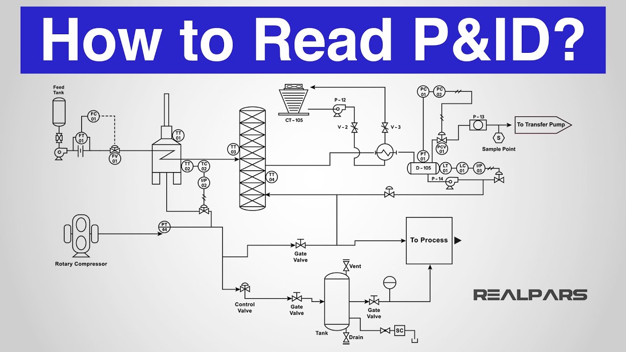
How to Read a P&ID? (Piping & Instrumentation Diagram) YouTube
Web A P&Id (Piping And Instrumentation Diagram) Is A Schematic Diagram Used In Process Engineering To Show The Flow Of Fluids And Gases Through A System, As Well As The Equipment And Instrumentation Used In The Process.
Web P&Ids Are A Schematic Illustration Of The Functional Relationship Of Piping, Instrumentation And System Equipment Components Used In The Field Of Instrumentation And Control Or Automation.
Web In This Video, You Will Learn The Basics Of Piping And Instrumentation Diagrams (Also Called P&Id Drawings).#Pipingandinstrumentation #Processcontrol #Instru.
Web A Piping And Instrumentation Diagram, Also Called P&Id, Is A Diagram Used To Show A Graphical Display Of A Complete System.
Related Post: