Mechanical Technical Drawing Symbols
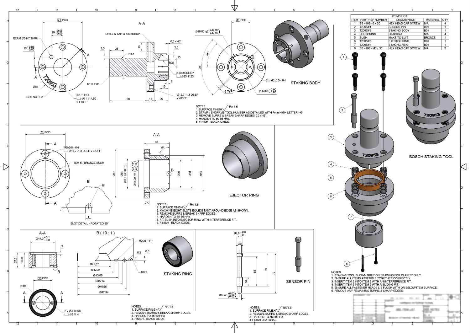
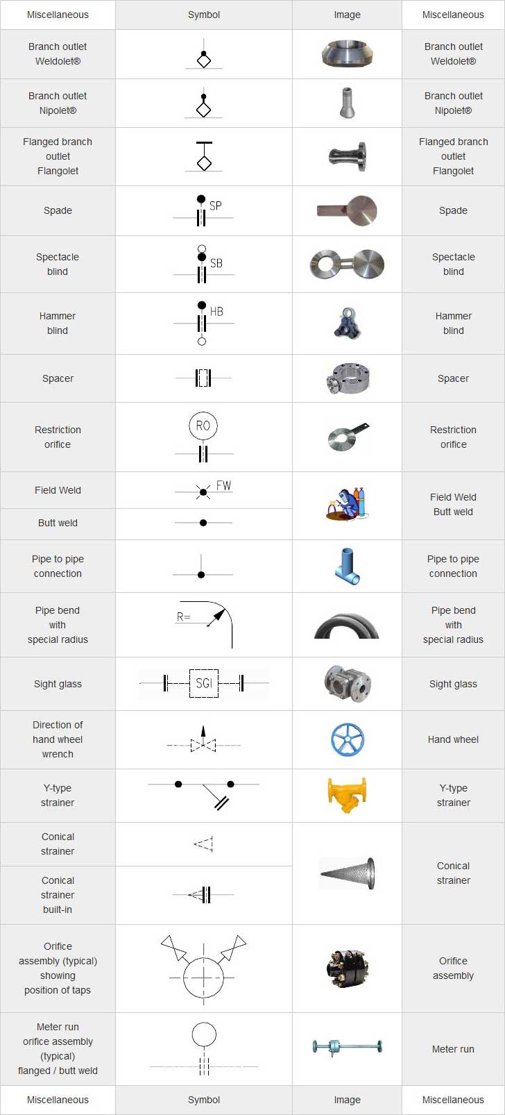
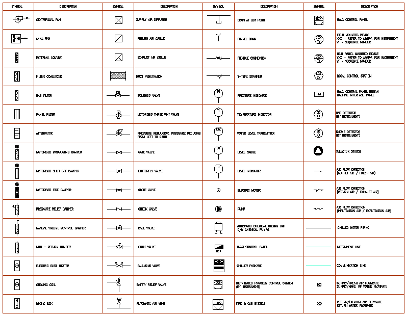
Mechanical Technical Drawing Symbols - Geometric tolerances are specified using symbols on a drawing. Here are more commonly used engineering drawing symbols and design elements as below. Web graphical symbols for use on mechanical engineering and construction drawings, diagrams, plans, maps and in relevant technical product documentation This list includes abbreviations common to the vocabulary of people who work with engineering drawings in the manufacture and inspection of parts and assemblies. Most symbols have been in y14.5 since at least 1994. If the drawing is made without either instruments or cad, it is called a freehand sketch. Dimensioning and tolerancing with 45 elements; Classification and symbols of geometric tolerance characteristics. Radius can be for the inside and outside curved surface on the part. 4 pdh a.bhatia continuing education and development, inc. Classification and symbols of geometric tolerance characteristics. Symbols or conventions used on the drawing and any additional information the designeror draftsmanfeltwas necessaryto understandthedrawing. If the drawing is made without either instruments or cad, it is called a freehand sketch. Web engineering drawing abbreviations and symbols are used to communicate and detail the characteristics of an engineering drawing. Geometric tolerances are. Here is a chart type featuring some commonly used engineering drawing symbols: 4 pdh a.bhatia continuing education and development, inc. The following tables show how to construct the symbols. They are used to help engineers and architects communicate with each other about the design of various objects. Web basic types of symbols used in engineering drawings are countersink, counterbore, spotface,. Web mechanical drawings, schematics, diagrams, plans, and maps are constructed using special graphical symbols, generally accepted in mechanical engineering. S220gd+z, s250gd+z, s280gd+z, s320gd+z, s350gd+z, s550gd+z • thickness: Any needed height h 2 h h 2 h 60° 2 h identification letter datum feature symbol datum target symbol target point and. Dimensioning and tolerancing with 45 elements; This list includes abbreviations. The ces headquarters is located in shanghai, home to some of the world’s leading manufacturers of harbour. Web crane & engineering services was established in 2009 as an independent business created from the technical services department of apm terminals, one of the world’s leading container terminal design, management and operating companies. From 0.25mm to 3.0mm, all available • width: Geometric. This helps to make technical documentation comprehensible and usable for all technical specialists and mechanical engineers. Web basic types of symbols used in engineering drawings are countersink, counterbore, spotface, depth, radius, and diameter. You can also check out the gd&t symbols and terms on our site. Web basic types of symbols used in engineering drawings are countersink, counterbore, spotface, depth,. To 1300mm, all available hot dip galvanized steel coil galvanized steel coil (production) galvanized steel coil. The ces headquarters is located in shanghai, home to some of the world’s leading manufacturers of harbour. Focusing on the technical drawing aspect of mechanical engineering design, the book shows exactly how to create technical. Web engineering drawing abbreviations and symbols are used to. Here are more commonly used engineering drawing symbols and design elements as below. From 0.25mm to 3.0mm, all available • width: Here are more commonly used engineering drawing symbols and design elements as below. 3d drawings n/a products fire protection system grooved piping. Web crane & engineering services was established in 2009 as an independent business created from the technical. The table shows dimensioning symbols found on drawings. Web the mechanical engineering drawing desk reference: 3d drawings n/a products fire protection system grooved piping. Web crane & engineering services was established in 2009 as an independent business created from the technical services department of apm terminals, one of the world’s leading container terminal design, management and operating companies. Classification and. From 0.25mm to 3.0mm, all available • width: This list includes abbreviations common to the vocabulary of people who work with engineering drawings in the manufacture and inspection of parts and assemblies. Web mechanical drawing symbols are used to represent physical objects in a technical drawing. Web engineering drawing abbreviations and symbols are used to communicate and detail the characteristics. S220gd+z, s250gd+z, s280gd+z, s320gd+z, s350gd+z, s550gd+z • thickness: The ces headquarters is located in shanghai, home to some of the world’s leading manufacturers of harbour. The following tables show how to construct the symbols. Dimensioning and tolerancing with 45 elements; Radius can be for the inside and outside curved surface on the part. Web the mechanical engineering discipline of the university of shanghai for science and technology offers master programs in mechanical design and theory, mechanical manufacturing and automation, mechanical electronic engineering and vehicle engineering (approved in 1984, 1986, 1996, 2006 respectively), as well as doctoral programs of the. Web engineering drawing abbreviations and symbols are used to communicate and detail the characteristics of an engineering drawing. If the drawing is made without either instruments or cad, it is called a freehand sketch. This list includes abbreviations common to the vocabulary of people who work with engineering drawings in the manufacture and inspection of parts and assemblies. Web crane & engineering services was established in 2009 as an independent business created from the technical services department of apm terminals, one of the world’s leading container terminal design, management and operating companies. Most symbols have been in y14.5 since at least 1994. Radius can be for the inside and outside curved surface on the part. Dimensioning and tolerancing with 45 elements; True position theory (size value in rectangular frame) You can also check out the gd&t symbols and terms on our site. Web basic types of symbols used in engineering drawings are countersink, counterbore, spotface, depth, radius, and diameter. They are used to help engineers and architects communicate with each other about the design of various objects. There are dozens of different symbols that can be used, but most share a few common elements. To 1300mm, all available hot dip galvanized steel coil galvanized steel coil (production) galvanized steel coil. Web graphical symbols for use on mechanical engineering and construction drawings, diagrams, plans, maps and in relevant technical product documentation Here are more commonly used engineering drawing symbols and design elements as below.
Mechanical Engineering Drawing Symbols Pdf Free Download at

Mechanical Engineering Drawing Symbols Pdf Free Download at

Mechanical Engineering Drawing Symbols Pdf Free Download at
M&e Drawing Symbols Back To Basics Komseq

Mechanical Drawing Symbols from Mechanical Engineering — Welding

Technical Drawing Symbols And Their Meanings Design Talk

Engineering Drawing Symbols And Their Meanings Pdf at PaintingValley

Mechanical Engineering Symbols Cadbull

Mechanical Drawing Symbols Mechanical Engineering Technical drawing

Mechanical Engineering Drawing Symbols Pdf Free Download at
Web Shanghai Vision Mechanical Joint Co., Ltd.
Web The Following Is A Short List Of Symbols That Normally Appear On A Technical Drawing And Need Understanding.
The Table Shows Dimensioning Symbols Found On Drawings.
The Following Tables Show How To Construct The Symbols.
Related Post: