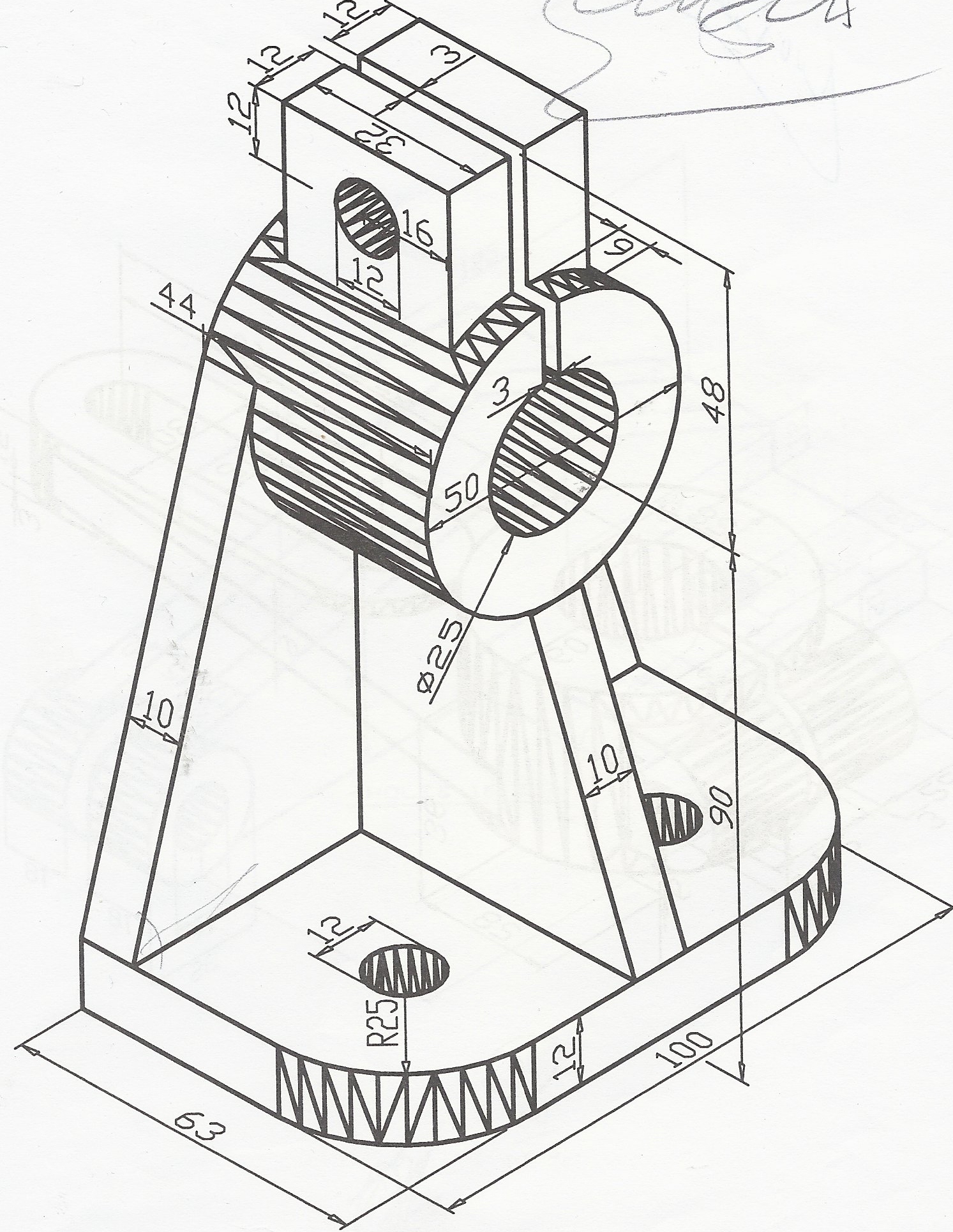
Mechanical Line Drawing
Mechanical Line Drawing - Web engineering drawings (aka blueprints, prints, drawings, mechanical drawings) are a rich and specific outline that shows all the information and requirements needed to manufacture an item or product. Web mechanical line drawing stock photos and images. They are drawn as solid lines with. This is likely a line quality that you have already used when you aren’t paying attention to how the lines you draw help to convey the meaning and context of your drawing. It is more than simply a drawing, it is a graphical language that communicates ideas and information. Web in an isometric drawing, the object’s vertical lines are drawn vertically, and the horizontal lines in the width and depth planes are shown at 30 degrees to the horizontal. Plus, mechanical pencils stay sharp, without needing to be sharpened. Freehand lines shows breaks or cuts in parts or assemblies. Two methods of dimensioning are in common use. Cut outs | vectors | black & white. Freehand lines shows breaks or cuts in parts or assemblies. They convey critical information, dimensions, and details that guide the construction of complex structures, machinery, and systems. When drawn under these guidelines, the lines parallel to these three. Short center lines (as opposed to the chain line) bending lines. Web their basic purpose is to show circular/cylindrical features in a. They are drawn as solid lines with. They give an exact representation of the object and show all parts in their true size relation. Engineering drawings use standardised language and symbols. Learning mechanical drawing is similar to learning another language. Freehand lines shows breaks or cuts in parts or assemblies. Usually, a number of drawings are necessary to completely specify even a simple component. Unidirectional, the dimensions are written horizontally. This is likely a line quality that you have already used when you aren’t paying attention to how the lines you draw help to convey the meaning and context of your drawing. 2 lines, lettering, and dimensions. Web mechanical systems. Freehand lines shows breaks or cuts in parts or assemblies. Web lines in engineering drawing are more than just strokes on paper; Web following are the different types of lines used in engineering drawing: See mechanical system line drawing stock video clips. A common use is to specify the geometry necessary for the construction of a component and is called. A common use is to specify the geometry necessary for the construction of a component and is called a detail drawing. Ala hijazi engineering working drawings basics page 10 of 22. Smartdraw works in both us/imperial and metric standards of measure and also allows you to customize the scale of your mechanical drawing. Cut outs | vectors | black &. It is a powerful tool. Web lines in engineering drawing are more than just strokes on paper; Smartdraw works in both us/imperial and metric standards of measure and also allows you to customize the scale of your mechanical drawing. Web following are the different types of lines used in engineering drawing: (15,309) see mechanical line drawing stock video clips. When drawn under these guidelines, the lines parallel to these three. Web mechanical line drawing stock photos and images. Web 18.06.2020 by andreas velling. In this comprehensive guide, we’ll delve into the diverse world of lines used in engineering drawings. Web their basic purpose is to show circular/cylindrical features in a drawing, which are found in abundance in mechanical parts. This helps to make technical documentation comprehensible and usable for all technical specialists and mechanical engineers. Web in an isometric drawing, the object’s vertical lines are drawn vertically, and the horizontal lines in the width and depth planes are shown at 30 degrees to the horizontal. The purpose is to convey all the information necessary for manufacturing a product or. Freehand lines shows breaks or cuts in parts or assemblies. An engineering drawing is a subcategory of technical drawings. Short center lines (as opposed to the chain line) bending lines. Web lines in engineering drawing are more than just strokes on paper; Aligned, the dimensions are written parallel to their dimension line. Web their basic purpose is to show circular/cylindrical features in a drawing, which are found in abundance in mechanical parts. This is likely a line quality that you have already used when you aren’t paying attention to how the lines you draw help to convey the meaning and context of your drawing. It is a teaching aid for high school. Aligned, the dimensions are written parallel to their dimension line. Two methods of dimensioning are in common use. Web mechanical line drawing stock photos and images. Web lines in engineering drawing are more than just strokes on paper; It is more than simply a drawing, it is a graphical language that communicates ideas and information. Line weight is the thickness of the line. Cut outs | vectors | black & white. Interpret dimensioning on technical drawings. Freehand lines shows breaks or cuts in parts or assemblies. Web following are the different types of lines used in engineering drawing: Usually, a number of drawings are necessary to completely specify even a simple component. Web this article contains exercises for art students who wish to produce contour line drawings, cross contour drawings, blind drawings and other types of line drawings. The purpose is to convey all the information necessary for manufacturing a product or a part. It is a powerful tool. 2 lines, lettering, and dimensions. Common examples of such features include bolt holes, pins, discs, etc.
Mechanical Drawings bartleby

Mechanical Engineering Drawing at GetDrawings Free download
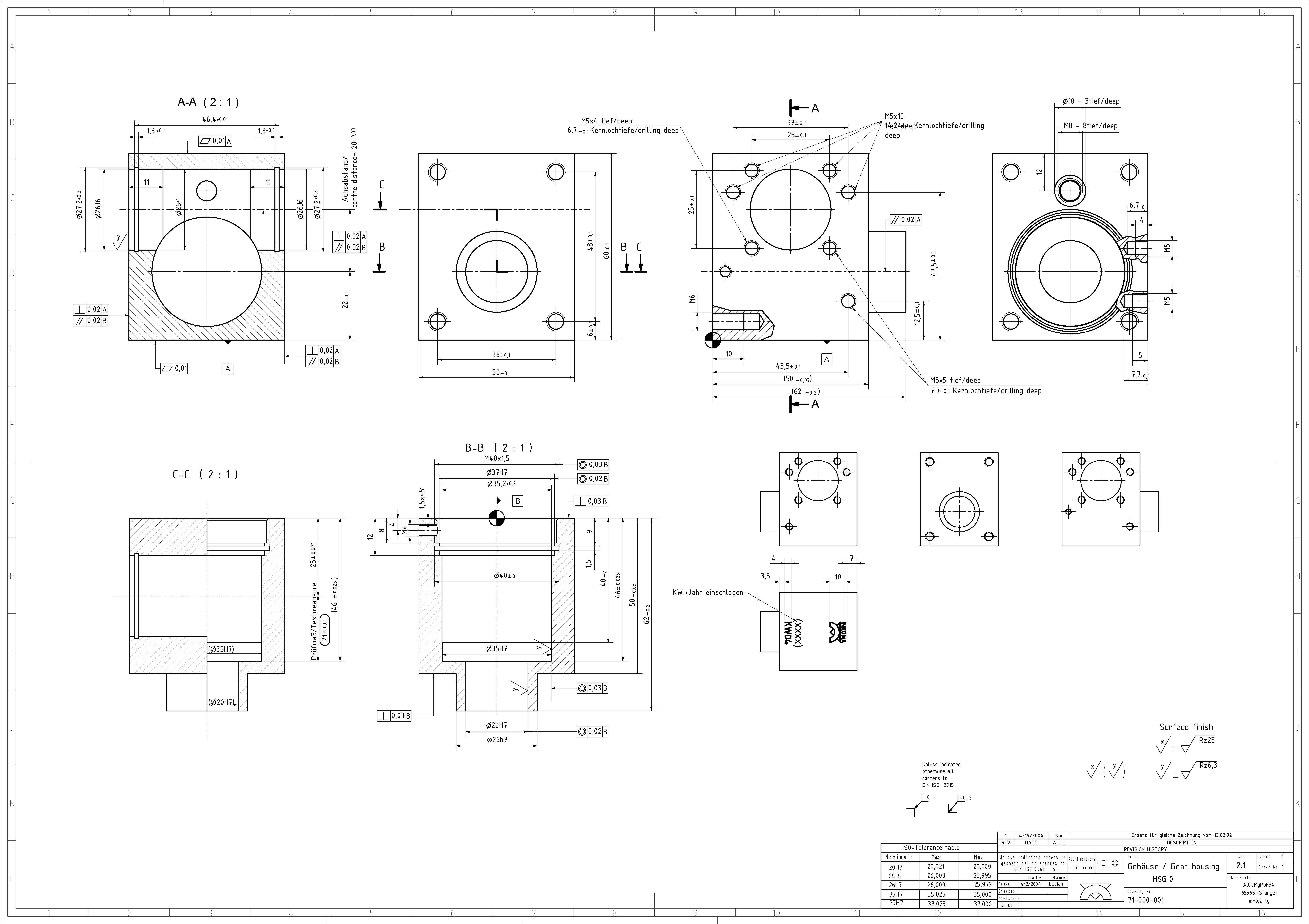
Autocad Mechanical Drawing Samples at GetDrawings Free download
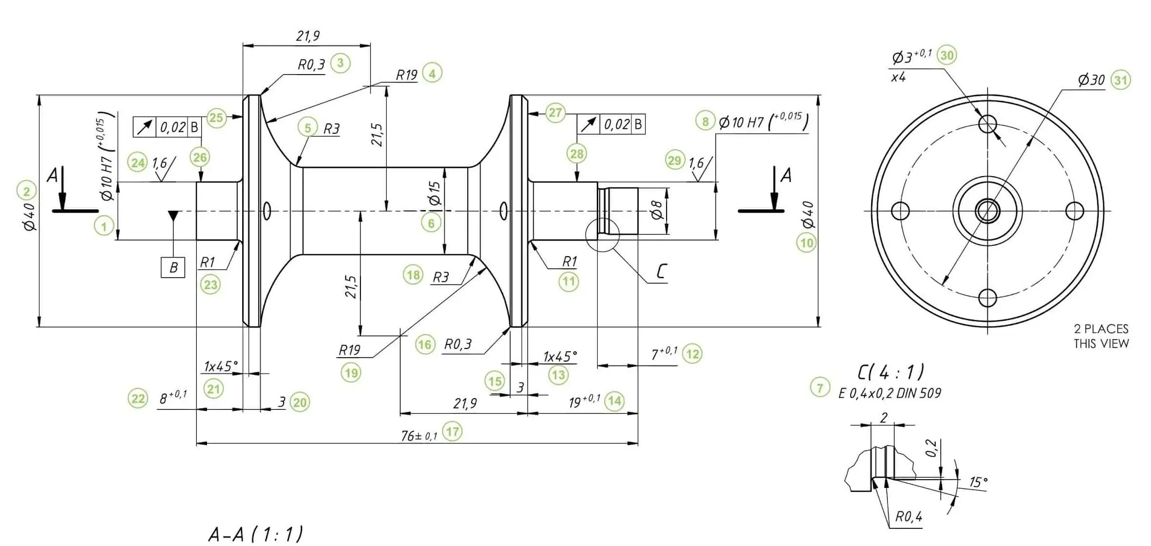
How To Prepare A Perfect Technical Drawing Xometry Europe
Mechanical Engineering Drawing at GetDrawings Free download

Mechanical engineering drawings on white Vector Image
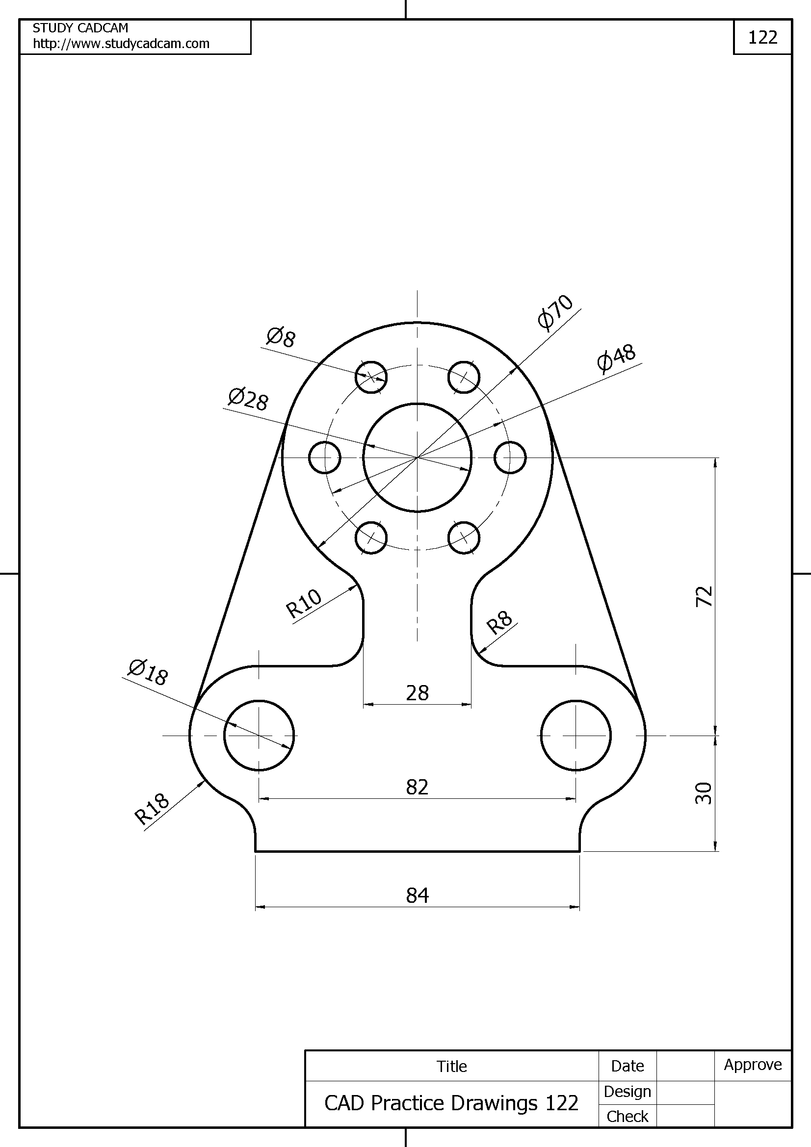
Autocad Mechanical Drawings at Explore collection

Mechanical Drawings bartleby
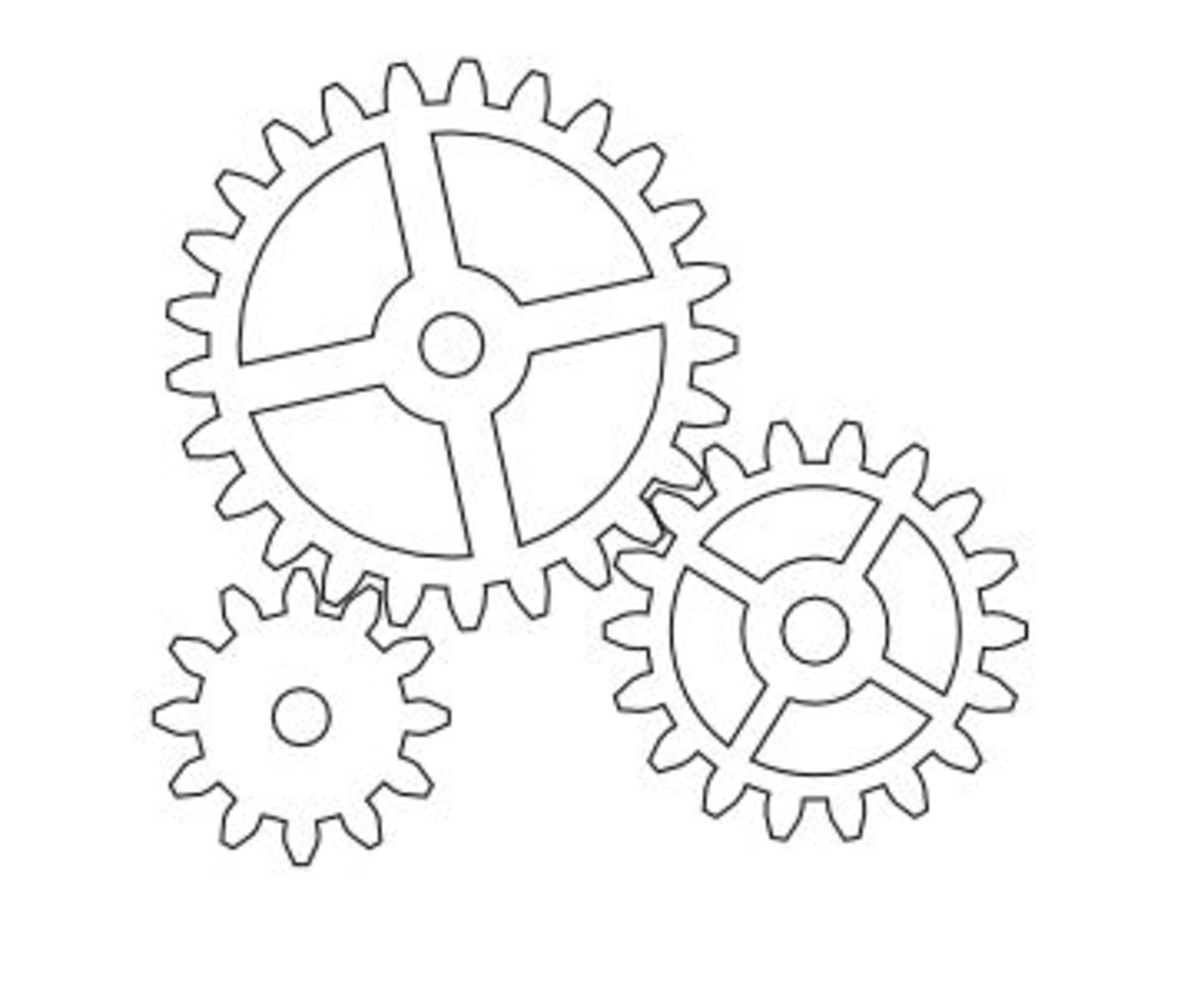
Mechanical Gears Drawing at Explore collection of

Mechanical Engineer Drawing at GetDrawings Free download
Short Center Lines (As Opposed To The Chain Line) Bending Lines.
They Give An Exact Representation Of The Object And Show All Parts In Their True Size Relation.
The Edge Of The Partial Or Interrupted View Is Indicated With A Freehand Line.
This Line Quality Is The Simplest, Most Straightforward Line Quality There Is In Drawing.
Related Post:
