Id Drawings
Id Drawings - Web the term p&id stands for piping and instrumentation diagram or drawing. Here's what we know about them. Identify, abstract, search, compare, modify engineering information from these drawings; Our streamlined p&id software makes it easy for piping designers and electrical, mechanical, and process engineers to create accurate depictions of piping structures and other related components. Corso systems describes the basic concepts of p&id drawings so you can read and understand them in the context of process control and automation. These diagrams provide a map for the engineering system's design which is helpful to problem identification and solving. These facilities have complex chemical or mechanical components and processes, which are modeled with diagrams. P&id diagrams are made with specific and standard shapes and symbols. Idrawings can be used to: Web p and id (piping and instrumentation diagram) is a schematic representation of a process system in the oil and gas, chemical, and other manufacturing industries. Web p and id (piping and instrumentation diagram) is a schematic representation of a process system in the oil and gas, chemical, and other manufacturing industries. Web as outdated as a drawing might seem in today's digital world, sketch artists serve a unique purpose by distilling hours of court into a cohesive image, according to sara w. Launch your browser. The full panel in donald trump's. P&id diagrams are made with specific and standard shapes and symbols. These facilities have complex chemical or mechanical components and processes, which are modeled with diagrams. Web a p&id is a working document that is used by every discipline involved in the design, engineering and construction of process plants. The winning numbers for saturday,. Web learn how process control, safety instrumented systems, interlock & alarms are represented in engineering p&id drawings. Web the term p&id stands for piping and instrumentation diagram or drawing. To read a p&id drawing, you must know what each symbol means and how each symbol is constructed. Such diagrams are famous in the engineering field. It is used as a. Web p&id symbols, which stand for piping and instrumentation diagram symbols, are graphical representations used in engineering and process industries to depict the process flow, equipment, instrumentation, and control systems of a system or a plant. In other words it is also called a process and instrumentation diagram or simply a p&i diagram or drawing. Web corso systems dives deeper. P&id software built with engineers in mind. These facilities have complex chemical or mechanical components and processes, which are modeled with diagrams. Identify, abstract, search, compare, modify engineering information from these drawings; As this diagram covers many types of diagrams as the variety in industries is vast, many symbols are required. 357k views 3 years ago basic instrumentation through animation. It's a simple way of using lines and symbols to tell the story of how liquids and gases move around, and how machines control them. 41k views 2 years ago instrumentation tools. Web corso systems dives deeper into p&id drawings with the next article in our understanding p&id drawings series. Here's what we know about them. In this video, you. Make a p&id with lucidchart. Our streamlined p&id software makes it easy for piping designers and electrical, mechanical, and process engineers to create accurate depictions of piping structures and other related components. Web a p&id is a working document that is used by every discipline involved in the design, engineering and construction of process plants. For this, you need to. Web learn how process control, safety instrumented systems, interlock & alarms are represented in engineering p&id drawings. It displays the piping and associated parts of a physical process flow. Web a p&id drawing, aka piping and instrument diagram, is a drawing that explains a physical process with the help of pipelines and other instruments present in the particular workflow or. These diagrams provide a map for the engineering system's design which is helpful to problem identification and solving. 357k views 3 years ago basic instrumentation through animation. It is used as a process plant layout and piping design reference for checking engineering and design documents and drawings associated with a project. P&ids are commonly called engineering flow drawings or. The. Web p and id (piping and instrumentation diagram) is a schematic representation of a process system in the oil and gas, chemical, and other manufacturing industries. During operation, you have to maintain p&id in such a condition that it will show actual plant conditions at any time. It displays the piping and associated parts of a physical process flow. The. Make a p&id with lucidchart. Web p&id drawing, or piping and instrumentation diagrams, is like a special map that shows how pipes and instruments work together in factories and plants. Web piping & instrumentation diagram explained. Web p and id (piping and instrumentation diagram) is a schematic representation of a process system in the oil and gas, chemical, and other manufacturing industries. It includes all piping, instruments, valves, and equipment the system consists of. It displays the piping and associated parts of a physical process flow. Through a p&id, you can get the following information: In this video, you will learn the basics of piping and instrumentation diagrams (also called p&id. Corso systems describes the basic concepts of p&id drawings so you can read and understand them in the context of process control and automation. Examples are piping layout, flowpaths, pumps, valves, instruments, signal modifiers, and controllers, as illustrated in. It is used as a process plant layout and piping design reference for checking engineering and design documents and drawings associated with a project. To read our blog on this. Winning lottery numbers are sponsored. Learn how temperature, pressure, and control systems and more are indicated in a real world example. 5 alternate jurors were selected friday. Web as outdated as a drawing might seem in today's digital world, sketch artists serve a unique purpose by distilling hours of court into a cohesive image, according to sara w.
New ID drawings drawings by MitzSweet on DeviantArt

Personal Id Card / Cartoon Vector And Illustration, Black And White
Id Drawing at Explore collection of Id Drawing

One continuous line drawing id card Royalty Free Vector

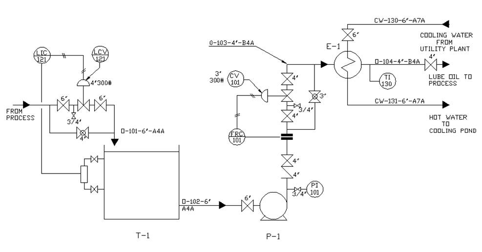
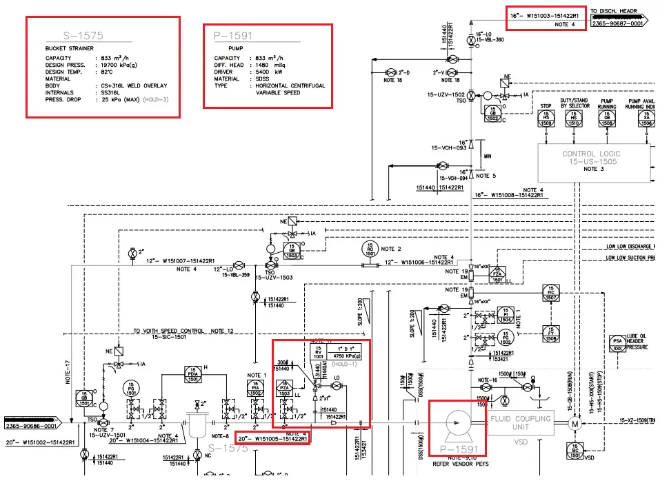
Learn How to Read P&ID Drawings A Complete Guide

Id Card Drawing Stock Vector 52893031 Shutterstock

Id Card Line Drawing Illustration Animation Stock Motion Graphics SBV

Cartoon Vector Illustration of Id Card 2392569 Vector Art at Vecteezy
Learn How To Read P Id Drawings Best Diagram Collecti vrogue.co

Learn How to Read P&ID Drawings A Complete Guide
Web Let Us Know!
Piping And Instrumentation Diagrams, Or P&Ids, Are Used To Create Important Documentation For Process Industry Facilities.
Our Streamlined P&Id Software Makes It Easy For Piping Designers And Electrical, Mechanical, And Process Engineers To Create Accurate Depictions Of Piping Structures And Other Related Components.
Web A Piping And Instrumentation Diagram, Also Called P&Id, Is A Diagram Used To Show A Graphical Display Of A Complete System.
Related Post: