How To Read Pipe Drawings
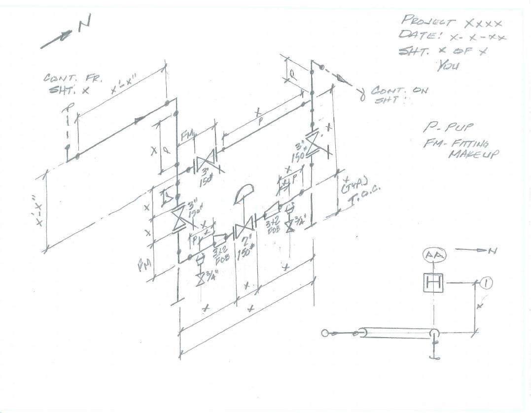
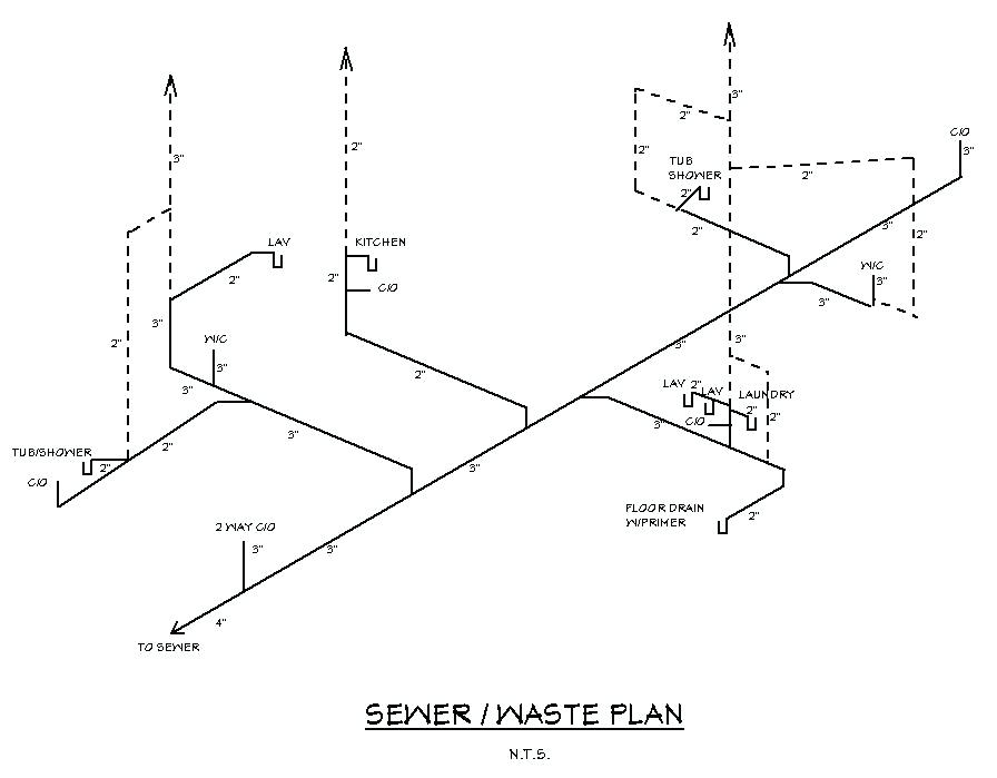
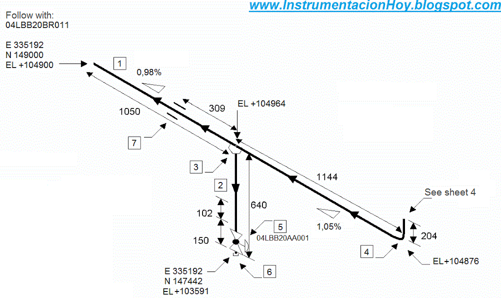
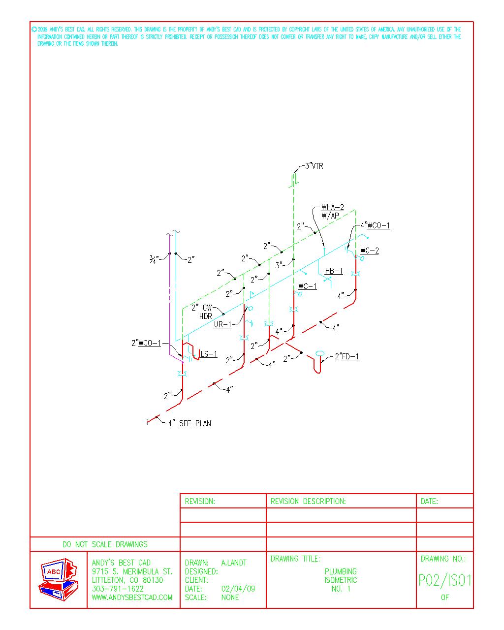
How To Read Pipe Drawings - Piping and pipeline drawing symbols throw lights on the type of joint like buttweld, socket weld, or threaded. Reading a piping isometric drawing basic training. A piping and instrumentation diagram, or p&id, shows the piping and related components of a physical process flow. Isometric drawing piping symbols serve as a ready reference for the type of fittings and components. The main graphic section consists of the isometric representation of the pipe line route in 3d space, and also includes the following details: In this article, you’ll learn what piping and instrumentation diagrams are and how to read them correctly. Learn how to draw the correct information from piping isometrics like a pro ( pipe fittings flanges valves isos.) highest rated. Piping isometrics demystified through practical examples. How to read isometric drawing in a piping isometrics drawing, pipe is drawn according to it’s. P&ids are foundational to the maintenance and modification of the process that it graphically represents. P&ids are foundational to the maintenance and modification of the process that it graphically represents. 66k views 1 year ago tutorials for pipe fitters and fabricators. • if pipe is in horizontal plane, the lettering will appear as if it is lying down and will be oriented Here, i have tried to explain p&id and pefs in an easy way.. Main graphic, bill of material, and title bar. P&ids are foundational to the maintenance and modification of the process that it graphically represents. The main graphic section consists of the isometric representation of the pipe line route in 3d space, and also includes the following details: 22k views 4 years ago reading isometric drawing. Web how to read a piping. Web knowing the piping drawing symbols will provide various information like: Here, i have tried to explain p&id and pefs in an easy way. A piping and instrumentation diagram, or p&id, shows the piping and related components of a physical process flow. Web how to read a piping isometric? Function and purpose of p&ids. The drawing axes of the isometrics intersect at an angle of 60°. 3.5+ hours of high quality video lessons. Web how to read piping isometrics using real plant drawings. Web understanding pipeline dimensions. Web here are a few aspects you should consider while reading a piping and instrumentation diagram. In this article, you’ll learn what piping and instrumentation diagrams are and how to read them correctly. Web p&id (piping & instrumentation diagram) & engineering drawings interpretation. This video explain about piping isometric drawing details 1.how to read isometric drawings_basic. Stephanus oscar, kaitlin harrington , suhendra lie. 254k views 2 years ago. This video explain about piping isometric drawing details 1.how to read isometric drawings_basic. Halley crast, andrew laskowski, maurice telesford, emily yatc. Web how to read piping isometrics using real plant drawings. The main graphic section consists of the isometric representation of the pipe line route in 3d space, and also includes the following details: Precise measurements are critical for selecting. What is covered in this course. Function and purpose of p&ids. What you will get in this course. 4.6 (191 ratings) 916 students. Here, i have tried to explain p&id and pefs in an easy way. It’s most commonly used in the engineering field. 3.5+ hours of high quality video lessons. Function and purpose of p&ids. Web understanding how to read pipeline isometric drawings. Web peter woolf et al. 254k views 2 years ago. • if pipe is in horizontal plane, the lettering will appear as if it is lying down and will be oriented We are concluding our first pipefitter series run with a video on how to draw isometric drawings. 2/5 in the series how to interpret piping and instrumentation diagrams. Halley crast, andrew laskowski, maurice telesford,. Precise measurements are critical for selecting suitable ndt equipment and ensuring comprehensive inspection coverage. 4.6 (191 ratings) 916 students. Web how to read a piping isometric? Isometric drawing piping symbols serve as a ready reference for the type of fittings and components. After exploring lots of videos and articles about p&ids we concluded that reading the valve symbols, lines, codes,. 254k views 2 years ago. Web a piping isometric drawing is a technical drawing that depicts a pipe spool or a complete pipeline using an isometric representation. What you will get in this course. Piping and pipeline drawing symbols throw lights on the type of joint like buttweld, socket weld, or threaded. We are concluding our first pipefitter series run with a video on how to draw isometric drawings. Here, i have tried to explain p&id and pefs in an easy way. Web piping technical trainer. In this article, you’ll learn what piping and instrumentation diagrams are and how to read them correctly. Halley crast, andrew laskowski, maurice telesford, emily yatc. It’s most commonly used in the engineering field. Dimensions and location of instruments. P&ids are foundational to the maintenance and modification of the process that it graphically represents. Piping iso symbols and meaning. Three main rules in isometric drawing. Pythagoras theorem (for rolling movement of pipe) let’s first focus to know what is a piping isometric? Piping and instrumentation diagrams (p&ids) use specific symbols to show the connectivity of equipment, sensors, and valves in a control system.
How to read iso pipe drawings perlogistics

How to read piping isometric drawing plmservers

How to read isometric drawing piping dadver

How to read piping isometric drawing plmservers

How to read piping isometric drawing, Pipe fitter training, Watch the

Piping Design Basics Piping Isometric Drawings Piping Isometrics

How to read pipe drawing? Isometric explanation YouTube

How to Read Basic Piping Isometric Drawings Piping Analysis YouTube

How to read piping Isometric drawing YouTube

How to read isometric drawing piping maznext
Piping Isometrics Demystified Through Practical Examples.
How To Read Isometric Drawing In A Piping Isometrics Drawing, Pipe Is Drawn According To It’s.
The Main Graphic Section Consists Of The Isometric Representation Of The Pipe Line Route In 3D Space, And Also Includes The Following Details:
Reading A Piping Isometric Drawing Basic Training.
Related Post: