How To Draw A Phasor Diagram
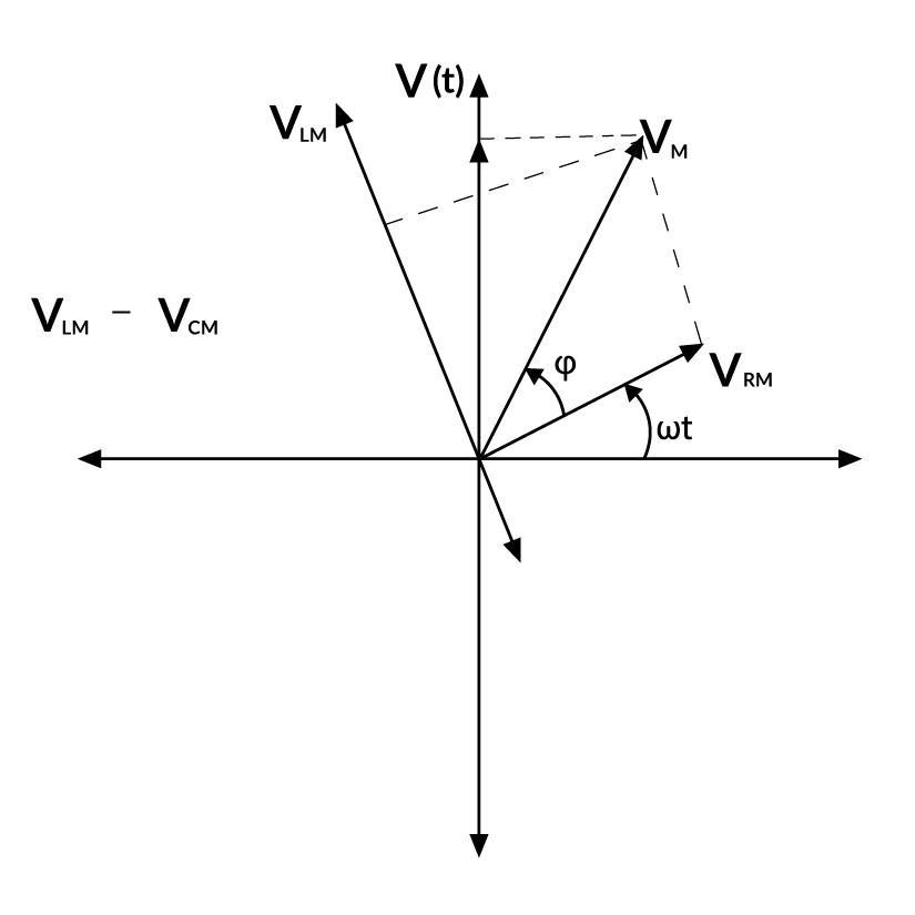
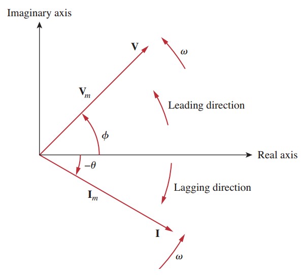
How To Draw A Phasor Diagram - In case of series rl circuit, resistor and inductor are connected in series, so current flowing in both the elements are same i.e i r = i l = i. There are two key ideas behind the phasor representation of a signal: They are also a useful tool to add/subtract oscillations. Y = xa b 0 < x < b. Colorado state university via openstax cnx. \(8 + j6\) and \(5 − j3\) (equivalent to \(10\angle 36.9^{\circ}\) and \(5.83\angle −31^{\circ}\)). Web a phasor diagram is a graphical representation of a sinusoidal waveform that is used to visualize the relative phase and amplitude of different components in the waveform. A = v sin p. Web in this video, phasor, and phasor diagram for ac circuits have been explained. There are five rules for drawing phasor diagrams. How to draw a phasor diagram of any circuit is discussed here step by step. They are also a useful tool to add/subtract oscillations. Imagine that the phasors are rotating in an anticlockwise (counter clockwise) direction. Web how do you draw a phasor diagram? Web phasor diagrams are a representation of an oscillating quantity as a vector rotating in phase. So, take current phasor as reference and draw it on horizontal axis as shown in diagram. Formula of relation between phase and line voltage and current. 29k views 2 years ago electrical interview question | basic. Web this demonstration shows a phasor diagram in an ac series rlc circuit. To draw a phasor diagram, you represent each voltage or current. In case of resistor, both voltage and current are in same phase. There are five rules for drawing phasor diagrams. Web for drawing the phasor diagram, take current phasor as reference and draw it on horizontal axis as shown in diagram. The current in an rlc series circuit is determined by the differential equation. B = v cos p. Web for drawing the phasor diagram of series rl circuit; Web interpret phasor diagrams and apply them to ac circuits with resistors, capacitors, and inductors. In case of resistor, both voltage and current are in same phase. In circuits which have l, c, r connected in series. Web phasor diagrams can be used to represent two or more stationary sinusoidal. Web a phasor diagram consists of vectors that represent the amplitude and phase of ac voltages and currents. Y = xa b b < x < 0. Web phasor diagrams can be used to represent two or more stationary sinusoidal quantities at any instant in time. It is customary to draw the phasor representing current horizontally, and call this the. To draw a phasor diagram, you represent each voltage or current phasor as a vector with its magnitude and phase angle. How to draw a phasor diagram of any circuit is discussed here step by step. Formula of relation between phase and line voltage and current. B = v cos p. 83k views 2 years ago alternating current. These vectors are represented by rotating arrows, where the length of the arrow represents the amplitude and the angle with respect to a reference axis represents the phase. To draw a phasor diagram, you represent each voltage or current phasor as a vector with its magnitude and phase angle. Web for drawing the phasor diagram, take current phasor as reference. The projection of the phasor onto an axis at a specific time gives the value of the quantity at that time. The current in an rlc series circuit is determined by the differential equation. B = v cos p. Web phasor diagrams are a representation of an oscillating quantity as a vector rotating in phase space with an angular velocity. Every phasor in the diagram will have the same. Web in the example phasor diagram of figure \(\pageindex{2}\), two vectors are shown: Imagine that the phasors are rotating in an anticlockwise (counter clockwise) direction. Web phasor diagrams are a representation of an oscillating quantity as a vector rotating in phase space with an angular velocity equal to the angular frequency. The projection of the phasor onto an axis at a specific time gives the value of the quantity at that time. B = v cos p. The vectors are then drawn on a common reference axis according to their respective angles to depict their relative positions and relationships. The current in an rlc series circuit is determined by the differential. To draw a phasor diagram, you represent each voltage or current phasor as a vector with its magnitude and phase angle. Web a phasor diagram is used to show the phase relationships between two or more sine waves having the same frequency. Web how to draw a phasor diagram? And at the end, voltage and current relationship between the basic circuit elements like resistor, inductor, and. Web discover how to draw accurate phasor diagrams with our comprehensive guide. 33k views 3 years ago #techtalks #howtodrawphasordiagram. In case of resistor, both voltage and current are in same phase. They are also a useful tool to add/subtract oscillations. Phasor diagrams can be used to plot voltages, currents and impedances. There are five rules for drawing phasor diagrams. Formula of relation between phase and line voltage and current. They are helpful in depicting the phase relationships between two or more oscillations. Web a phasor diagram consists of vectors that represent the amplitude and phase of ac voltages and currents. B = v cos p. Phasors are rotating vectors having the length equal to the peak value of oscillations, and the angular speed equal to the angular frequency of. How to draw a phasor diagram of any circuit is discussed here step by step.
Basic Phasor Diagram Electric Circuit
Introduction to Phasors Definition, Examples, Diagrams, and FAQs

Phasor Diagram For Inductive Circuit

How To Work & Draw Phasor Diagram Of Transformer At No Load YouTube
How to draw phasor diagram

How to draw phasor diagram from polar form phasors ? Electrical

How to draw a Phasor Diagram ? Step by Step Tech TALKS YouTube
What is Phasor and Phasor Diagram Simple Explanation Wira Electrical

How to draw Phasor diagram I Sinusoid I Phasor domain representation I
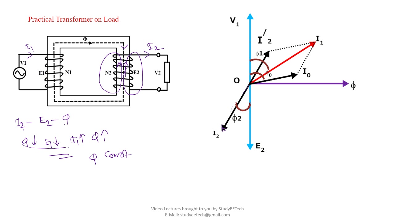
How to Draw Transformer Phasor Diagram YouTube
Web How Do You Draw A Phasor Diagram?
Y = Xa B 0 < X < B.
Web A Phasor Diagram Is A Graphical Representation Of A Sinusoidal Waveform That Is Used To Visualize The Relative Phase And Amplitude Of Different Components In The Waveform.
Colorado State University Via Openstax Cnx.
Related Post: