Esp32 Current Draw
Esp32 Current Draw - Regulated power to gnd and 3.3v pins. It also measures the voltage of a source. This section introduces how to measure the current consumption of a module running such an application. You might need a big capacitor from which energy is sourced then. Use a coulomb counter, e.g. I just want to make sure that the 5a stated maximum current output of the xl4015 is enough to power 2 esp32s and 12 relays reliably and in a stable manner. Web at 10v input voltage, the current draw was 99.9ma. Web while you can get 500ma from it, you can't do it continuously from 5v as it will overheat the regulator. The developer boards as specked out to having a 3v3 ldo that should supply 250ma. Web according to the datasheet of the esp32, the power consumption in deep sleep mode (rtc) is around 10µa. Web esp32 supports two major power saving modes: According to the esp32 datasheet, the power consumption during rf operations in active mode is as follows: Regulated power to gnd and 3.3v pins. During deep sleep the current is 135µa (0.135ma). Web while you can get 500ma from it, you can't do it continuously from 5v as it will overheat the. Web under full load, the circuit including the esp32 draws around 200ma at full load. Web it has also been observed that the chip draws more than 790 ma at times, particularly when both wifi and bluetooth are used simultaneously. You can connect a regulated 3.3v voltage supply to the 3.3v and gnd pins. I tried googling this and couldn’t. 250ma is the esp 32's max current draw with every gpio pin on and every api module in use. Web low power friendly! Configuration power management can be enabled at compile time, using the option config_pm_enable. There is also a $20 gps gp1818mk module. Web while you can get 500ma from it, you can't do it continuously from 5v as. Turn off the neopixel and external i2c power for the lowest quiescent current draw. Your current will vary quickly as the esp32 rtos is. Web at 10v input voltage, the current draw was 99.9ma. The additional component is controlled by a switch. Web a better approach to testing current draw is to get a esp32 test board. Change env:esp32cam to env:esp32dev in platformio.ini cause we cut off some memory. According to the features used by an application, there are some sub sleep modes. Another option that you have is to power your esp32 is to use a 3.3v regulated power supply. I just want to make sure that the 5a stated maximum current output of the xl4015. I've used the ltc4150 before, available here: Web while you can get 500ma from it, you can't do it continuously from 5v as it will overheat the regulator. We use this to power the esp32 which draws about 200ma continuous. There is also a $20 gps gp1818mk module. Where is 10ua ?!add adc_power_off (); You can connect a regulated 3.3v voltage supply to the 3.3v and gnd pins. This section introduces how to measure the current consumption of a module running such an application. In this tutorial, i am going to use the following parts, so if you want to try this tutorial yourself you need the following: Another option that you have is. Web at 10v input voltage, the current draw was 99.9ma. Web under full load, the circuit including the esp32 draws around 200ma at full load. See sleep modes for these sleep modes and sub sleep modes. Web no, there is no 3.3 pin on the esp32. an esp32 is just a chip. Web the question is, how much current could. Web at 10v input voltage, the current draw was 99.9ma. Web esp32 supports two major power saving modes: For this, you will use the 3.3 volt and gnd pins. Web low power friendly! At 5v, the current draw was 128ma. Please budget 250ma for the wroom32 module. Its compact design facilitates easy inline. Now i'd like to add another component, which is not controlled by the esp32 but uses the same +5v net to be powered. Let see ov2640 camera datasheet. Web it has also been observed that the chip draws more than 790 ma at times, particularly when both. There is also a $20 gps gp1818mk module. As we'll see, the current is not exactly what we expect. This mode, without a doubt, consumes the most current and is the least efficient. During deep sleep the current is 135µa (0.135ma). Regulated power to gnd and 3.3v pins. In deep sleep mode we can get down to 80~100ua of current draw from the lipoly connection. You can connect a regulated 3.3v voltage supply to the 3.3v and gnd pins. I just want to make sure that the 5a stated maximum current output of the xl4015 is enough to power 2 esp32s and 12 relays reliably and in a stable manner. According to the features used by an application, there are some sub sleep modes. I've used the ltc4150 before, available here: I use 330 ohm resisters to drive a single external led. Presumably you're talking about some devboard with an esp32 on it. The additional component is controlled by a switch. You can connect a regulated 3.3v voltage supply to the 3.3v and gnd pins. Wemos d1 mini v4 board power consumption in deep sleep. But, you don't say which one, so your question is impossible to answer.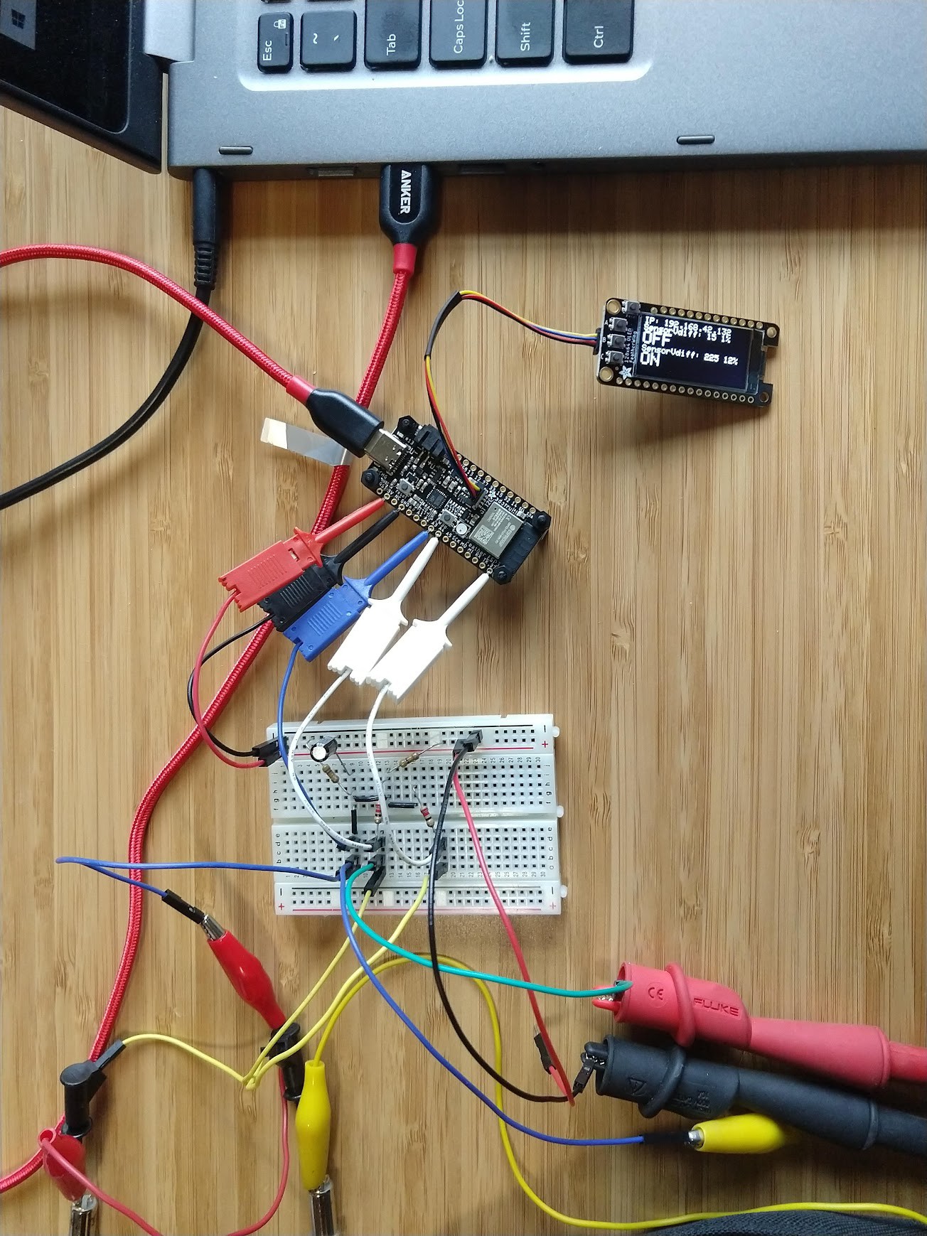
Gallery ESP32 Current Sensor with WiFi Hackaday.io

How to power your ESP32 development kit, options
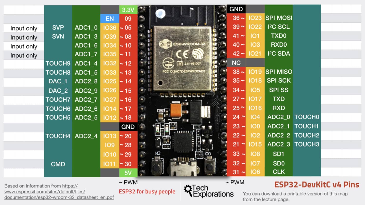
Lesson 4 The ESP32 GPIOs Tech Explorations

MEAM.Design ESP32 Board Pinout & Functionality
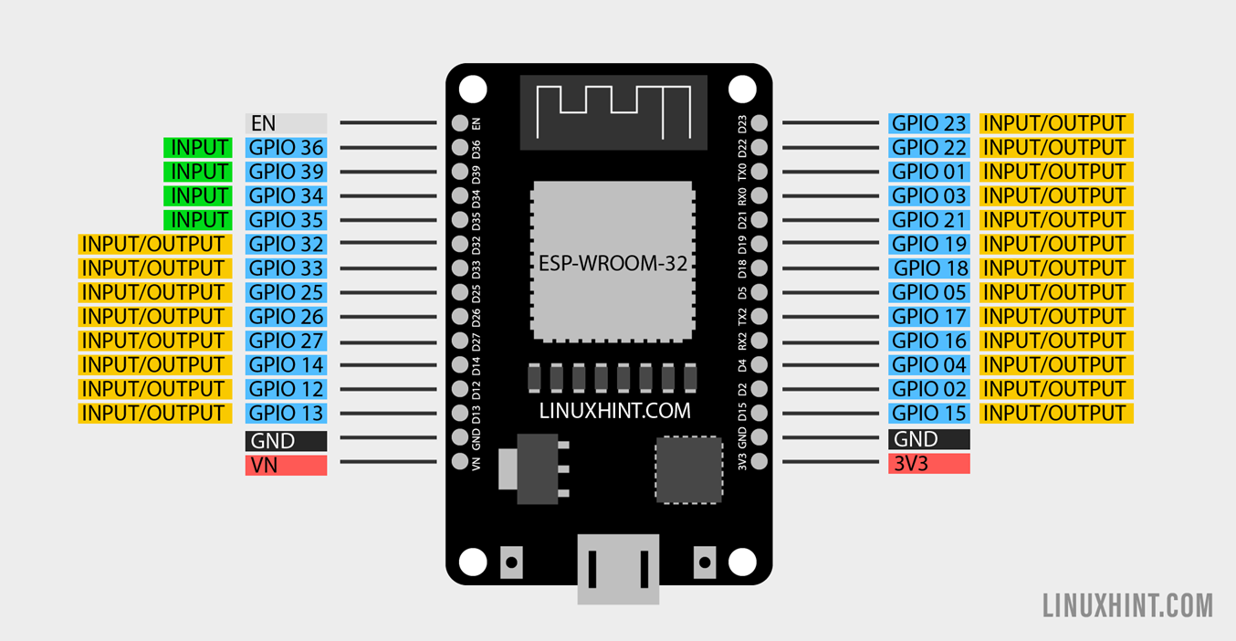
ESP32 Digital Inputs and Digital Outputs Using Arduino IDE Linux
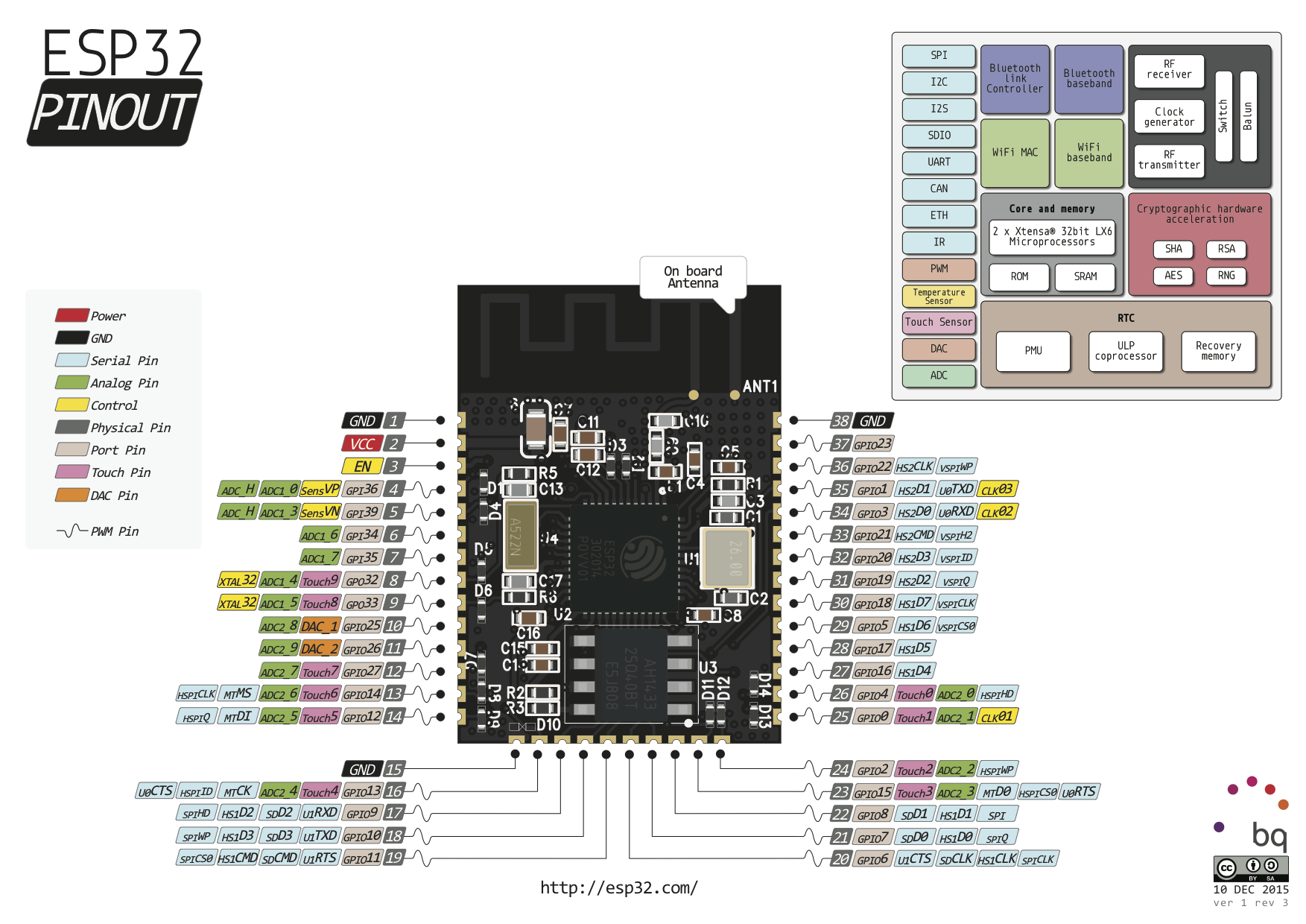
ESP32 Development Boards for WiFi communication Behind The Scenes

How can I use a SCT013000 to measure current using a ESP32? r
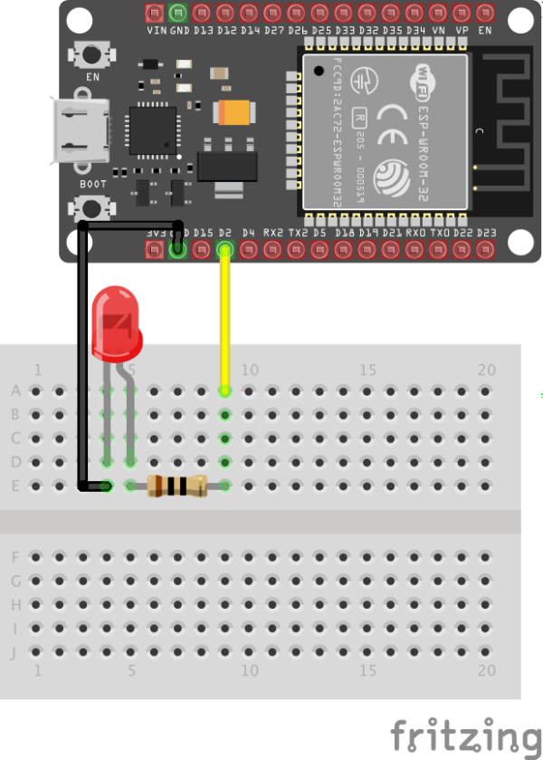
Getting Started with ESP32
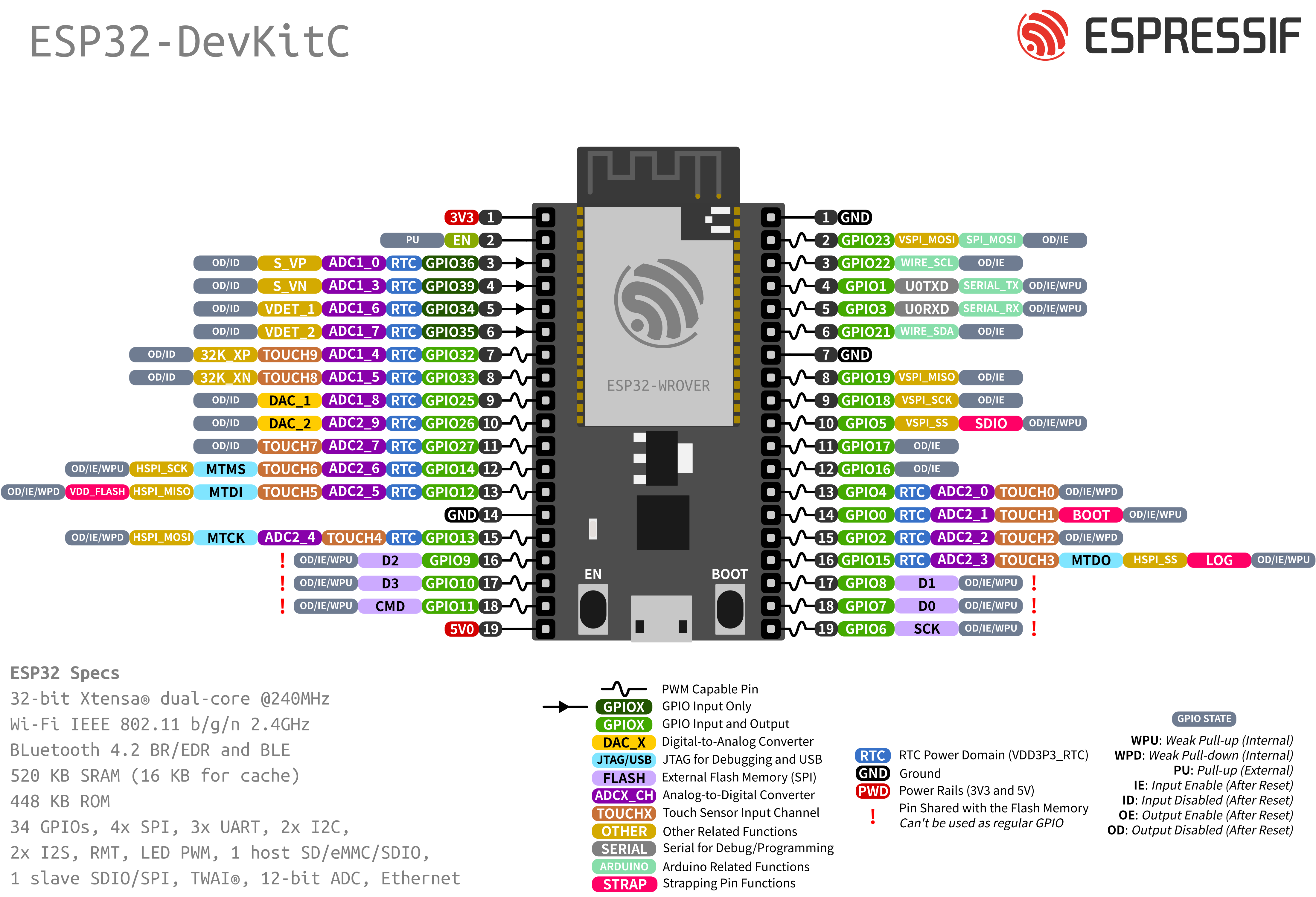
ESP32DevKitC1 — Arduino ESP32 latest documentation
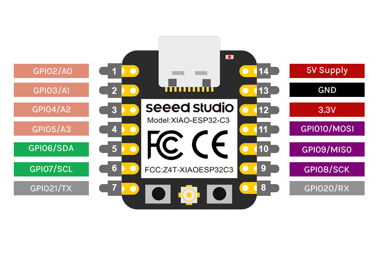
ESP32C3 Pinout, Datasheet, Features and Specs
Let See Ov2640 Camera Datasheet.
At 5V, The Current Draw Was 128Ma.
We Use This To Power The Esp32 Which Draws About 200Ma Continuous.
Web Low Power Friendly!
Related Post: