Engg Drawing Symbols
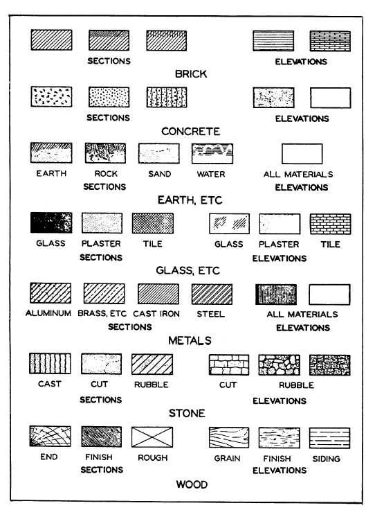
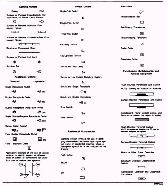
Engg Drawing Symbols - The table shows dimensioning symbols found on drawings. An engineering drawing is a subcategory of technical drawings. Web a convenient guide for geometric dimensioning and tolerancing (gd&t) symbols at your fingertips. For example, cold rolled steel is often abbreviated as crs, and diameter is often abbreviated as dia, d, or ⌀. Engineering drawings use standardised language and symbols. Unlike a model, engineering drawings offer more specific detail and requirements, such as: Unlike a model, engineering drawings note much more specific information and requirements, such as: Engineering design manufacturing definitions and terms. The dimensional symbols are the representation of symbols that used in engineering drawings, blueprints and technical diagrams. These symbols carry specific meanings and convey vital information about various facets of a design. The following is a short list of symbols that normally appear on a technical drawing and need understanding. Web engineering drawing abbreviations and symbols are used to communicate and detail the characteristics of an engineering drawing. Learners examine the drawing symbols used for counterbore, countersink, spotface, radius, diameter, and depth. These symbols carry specific meanings and convey vital information about. Here are more commonly used engineering drawing symbols and design elements as below. The following is a short list of symbols that normally appear on a technical drawing and need understanding. We offer you our tips which we believe are useful for dispelling uncertainty by comparing the symbol with its graphic representation. Web engineering drawing abbreviations and symbols are used. Web here are some commonly used engineering symbols are as follows, 1. Web engineering drawing abbreviations and symbols are used to communicate and detail the characteristics of an engineering drawing. Web a convenient guide for geometric dimensioning and tolerancing (gd&t) symbols at your fingertips. It is more than simply a drawing, it is a graphical language that communicates ideas and. Web this section standardizes the symbols for specifying geometrical characteristics and other dimensional requirements on engineering drawings. Click on the links below to learn more about each gd&t symbol or concept, and be sure to download the free wall chart for a quick reference when at your desk or on the shop floor. The following is a short list of. Engineering drawings use standardised language and symbols. Web engineering working drawings basics. For example, cold rolled steel is often abbreviated as crs, and diameter is often abbreviated as dia, d, or ⌀. Web basic types of symbols used in engineering drawings are countersink, counterbore, spotface, depth, radius, and diameter. Unlike a model, engineering drawings offer more specific detail and requirements,. It is more than simply a drawing, it is a graphical language that communicates ideas and information. Web here are some commonly used engineering symbols are as follows, 1. An engineering drawing is a subcategory of technical drawings. An introduction to the different types of blueprint tolerances you will encounter with plenty of examples to make them easy to understand.. Web this section standardizes the symbols for specifying geometrical characteristics and other dimensional requirements on engineering drawings. In the quiz that completes the activity, they associate these symbols with machining applications. These symbols carry specific meanings and convey vital information about various facets of a design. Web this chapter will introduce the five common categories of drawings. The table shows. The purpose is to convey all the information necessary for manufacturing a product or a part. In the quiz that completes the activity, they associate these symbols with machining applications. Learners examine the drawing symbols used for counterbore, countersink, spotface, radius, diameter, and depth. Gd&t symbols, iso g&t symbols 1101 definitions. Note the comparison with the iso standards. Engineering graphics is an effective way of communicating technical ideas and it is an essential tool in engineering design where most of the design process is graphically based. Web the gsfc engineering drawing standards manual is the official source for the requirements and interpretations to be used in the development and presentation of engineering drawings and related documentation for the. An introduction to the different types of blueprint tolerances you will encounter with plenty of examples to make them easy to understand. Web engineering working drawings basics. Unlike a model, engineering drawings offer more specific detail and requirements, such as: Engineering design manufacturing definitions and terms. Web here are some commonly used engineering symbols are as follows, 1. Many additional symbols are listed and described in this section, including symbols for datums, modifiers,. Note the comparison with the iso standards. Engineering graphics is an effective way of communicating technical ideas and it is an essential tool in engineering design where most of the design process is graphically based. Web engineering drawing symbols are like a secret language that only engineers can decode. Engineering drawings use standardised language and symbols. Web engineering working drawings basics. The following is a short list of symbols that normally appear on a technical drawing and need understanding. These symbols and abbreviations are standardized by the american national standards institute (asmi) and the american society of mechanical engineers (asme) in the us. Web as in many technical fields, a wide array of abbreviations and symbols have been developed in engineering drawing during the 20th and 21st centuries. An engineering drawing is a subcategory of technical drawings. These symbols carry specific meanings and convey vital information about various facets of a design. Learners examine the drawing symbols used for counterbore, countersink, spotface, radius, diameter, and depth. The following are definitions commonly used throughout industry when discussing gd&t or composing engineering drawing notes. Mechanical design is an important step in creating and designing mechanical elements, components, products, and systems. Need to know for dispelling uncertainty in drawings. An introduction to the different types of blueprint tolerances you will encounter with plenty of examples to make them easy to understand.
Mechanical Engineering Drawing Symbols Pdf Free Download at

Technical Drawing Symbols And Their Meanings Design Talk

Engineering Drawing Symbols And Their Meanings Pdf at GetDrawings

Engineering Drawing Symbols And Their Meanings Pdf at PaintingValley
Engineering Drawing Symbols And Their Meanings Pdf at PaintingValley

Engineering Drawing Symbols And Their Meanings Pdf at PaintingValley

Engineering Drawing Symbols List Chart Explain Mechanical Drawing

Engineering Drawing Symbols And Their Meanings Pdf at PaintingValley
Engineering Drawing Symbols And Their Meanings Pdf at PaintingValley

BASIC OF ENGINEERING DRAWING SYMBOL PART 1 YouTube
Web Here Are Some Commonly Used Engineering Symbols Are As Follows, 1.
Web Engineering Drawing Abbreviations And Symbols Are Used To Communicate And Detail The Characteristics Of An Engineering Drawing.
Web How To Read An Engineering Drawing Symbol.
Web Engineering Drawing Symbols Are Simple To Pick Up And Use Once You Understand How To Read Them.
Related Post: