Drawing Symbols Meaning
Drawing Symbols Meaning - Web electrical symbols and electronic circuit symbols are used for drawing schematic diagram. Web for example, engineering symbols are used in technical drawings to convey the specific geometry and other details about pieces of equipment or components. Web drafting symbols symbols provide a “common language” for drafters all over the world. Web symbols in mechanical drawings are graphical elements accepted by standards and codes. Standardized line types were developed for use in the industry. Click on the links below to learn more about each gd&t symbol or concept,. Web lines on a drawing have their own special meaning and purpose. Web how to read an engineering drawing symbol. Web drafting symbols reference sheet: Web engineering drawing abbreviations are a set of standardized symbols and abbreviations used on engineering drawings to represent common terms and phrases. Web some common engineering drawing symbols include geometric symbols (circle, square, triangle), symbols for surface finish (roughness, smoothness), symbols for welding. Web for example, engineering symbols are used in technical drawings to convey the specific geometry and other details about pieces of equipment or components. Web symbols in mechanical drawings are graphical elements accepted by standards and codes. You can. Web how to read an engineering drawing symbol. Web drafting symbols reference sheet: You can also check out the gd&t symbols. Web drafting symbols symbols provide a “common language” for drafters all over the world. The symbols represent electrical and electronic components. Here are more commonly used engineering drawing symbols and design elements as below. Engineering drawings are technical diagrams and representations meant to. Geometric tolerances are specified using symbols on a drawing. Web symbols in mechanical drawings are graphical elements accepted by standards and codes. These line types are referred to as the alphabet. General dimensioning symbols are shown. Web various symbols and abbreviations in engineering drawings give you information about the dimensions, design, and materials used. Web the table shows dimensioning symbols found on drawings. Web symbols in mechanical drawings are graphical elements accepted by standards and codes. Web for example, engineering symbols are used in technical drawings to convey the specific geometry. Engineering drawings are technical diagrams and representations meant to. The distance all the way across a circle. The following is a short list of symbols that normally appear on a technical drawing and need understanding. Here are more commonly used engineering drawing symbols and design elements as below. General dimensioning symbols are shown. Standardized line types were developed for use in the industry. The distance from the center of a circle to the edge. This handy guide includes everything from property lines and electrical symbols to elevation. Web some common engineering drawing symbols include geometric symbols (circle, square, triangle), symbols for surface finish (roughness, smoothness), symbols for welding. Click on the links below. Engineering drawings are technical diagrams and representations meant to. Need to know for dispelling uncertainty in drawings. Web drafting symbols symbols provide a “common language” for drafters all over the world. Learn the ins and outs of engineering drawing standards, such as iso and ansi, which govern the symbols,. Web drafting symbols reference sheet: The distance all the way across a circle. General dimensioning symbols are shown. Here are more commonly used engineering drawing symbols and design elements as below. You can also check out the gd&t symbols. The following is a short list of symbols that normally appear on a technical drawing and need understanding. Web basic types of symbols used in engineering drawings are countersink, counterbore, spotface, depth, radius, and diameter. Note the comparison with the iso standards. Web engineering drawings (aka blueprints, prints, drawings, mechanical drawings) are a rich and specific outline that shows all the information and requirements needed to. Web some common engineering drawing symbols include geometric symbols (circle, square, triangle),. The following is a short list of symbols that normally appear on a technical drawing and need understanding. Here are more commonly used engineering drawing symbols and design elements as below. Geometric tolerances are specified using symbols on a drawing. Web symbols in mechanical drawings are graphical elements accepted by standards and codes. Web electrical symbols and electronic circuit symbols. Web engineering drawings (aka blueprints, prints, drawings, mechanical drawings) are a rich and specific outline that shows all the information and requirements needed to. The reasons for using geometric. They represent components, elements, details, characteristics, actions, features,. It is a system of symbols and standards used by engineers to provide manufacturing information to the production team. Engineering drawings are technical diagrams and representations meant to. Web electrical symbols and electronic circuit symbols are used for drawing schematic diagram. Web drafting symbols symbols provide a “common language” for drafters all over the world. Web some common engineering drawing symbols include geometric symbols (circle, square, triangle), symbols for surface finish (roughness, smoothness), symbols for welding. The following is a short list of symbols that normally appear on a technical drawing and need understanding. Web gd&t drawings and symbols. Geometric tolerances are specified using symbols on a drawing. This handy guide includes everything from property lines and electrical symbols to elevation. General dimensioning symbols are shown. Currently, we have 16 symbols for geometric tolerances, which are. Web engineering drawing abbreviations are a set of standardized symbols and abbreviations used on engineering drawings to represent common terms and phrases. Learn the ins and outs of engineering drawing standards, such as iso and ansi, which govern the symbols,.
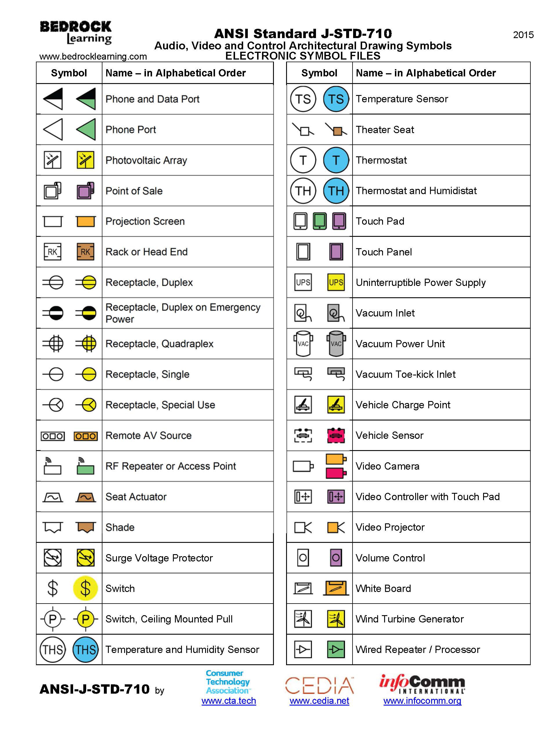
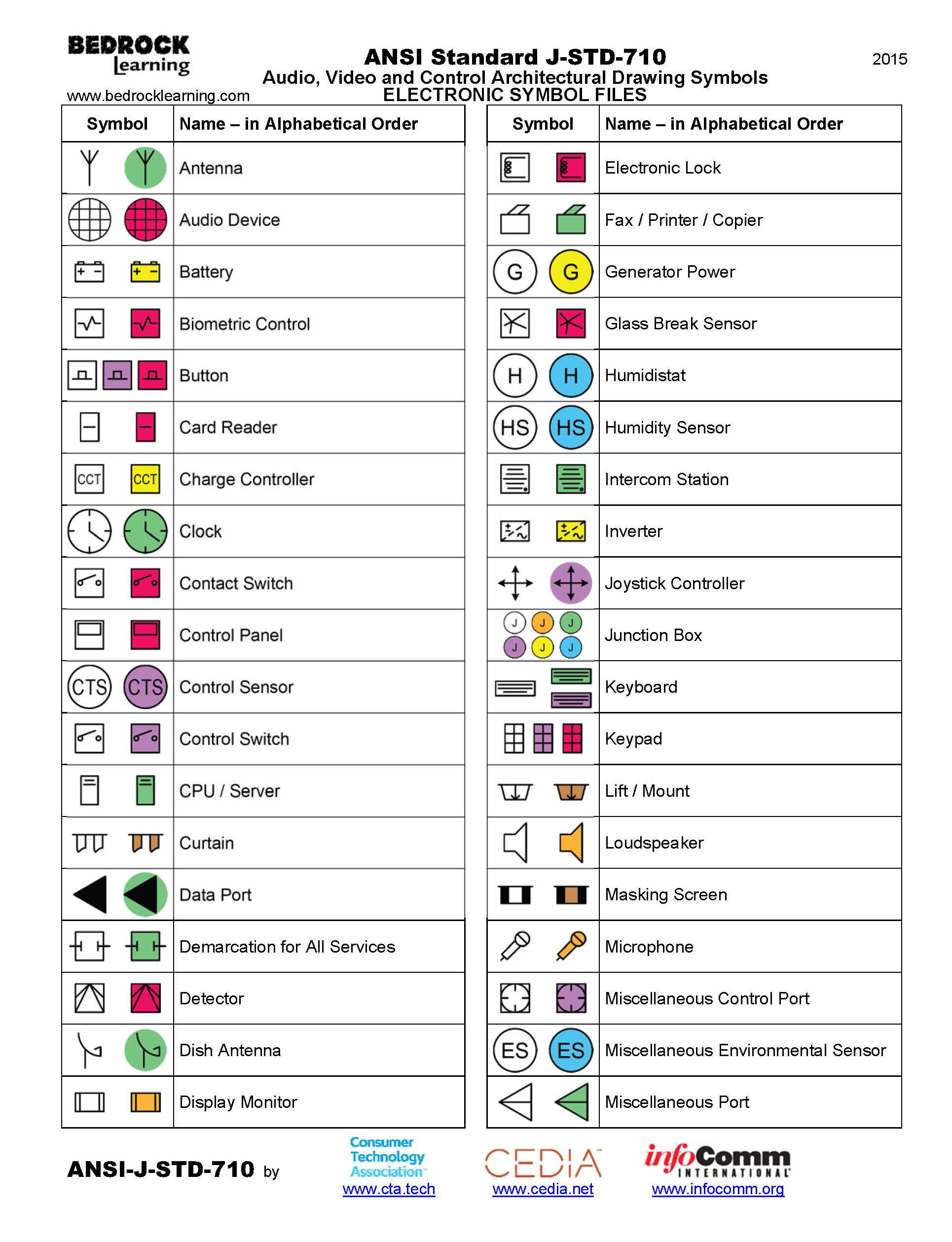
ANSI Standard JSTD710 Architectural Drawing Symbols Bedrock Learning

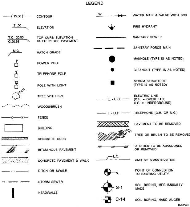
Civil Engineering Drawing Symbols And Their Meanings at PaintingValley

How To Read Architectural Drawings Symbols The Architect

Engineering Drawing Symbols And Their Meanings Pdf at PaintingValley

ANSI Standard JSTD710 Architectural Drawing Symbols Bedrock Learning

Technical Drawing Symbols And Their Meanings Design Talk

Engineering Drawing Symbols And Their Meanings Pdf at PaintingValley

Civil Engineering Drawing Symbols And Their Meanings at PaintingValley

Engineering Drawing Symbols And Their Meanings Pdf at PaintingValley

Engineering Drawing Symbols List Chart Explain Mechanical Drawing
Need To Know For Dispelling Uncertainty In Drawings.
The Distance All The Way Across A Circle.
You Can Also Check Out The Gd&T Symbols.
Web Drafting Symbols Reference Sheet:
Related Post: