Draw Shear And Moment Diagrams For The Beam
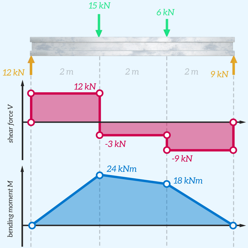
Draw Shear And Moment Diagrams For The Beam - 291k views 2 years ago engineering statics. 90k views 3 years ago statics. (9) 9 × 0 2 3 ∴ r = 9 kn. Learn to draw shear force and moment diagrams using 2 methods, step by step. Massachusetts institute of technology via mit opencourseware. [latex]\delta m=\int v (x)dx [/latex] (equation 6.2) equation 6.2 states that the change in moment equals the area under the shear diagram. Equation 6.1 suggests the following expression: Shear and bending moment diagrams. Web calculate bending moment diagrams. Web below is a simple example of what shear and moment diagrams look like, afterwards, the relation between the load on the beam and the diagrams will be discussed. This is a very useful skill to be good at for statics and mechanics of materials. In general the process goes like this:. Welcome to our free beam calculator! In particular, they identify the maximum values of v and m. Web below is a simple example of what shear and moment diagrams look like, afterwards, the relation between the load. [latex]\delta m=\int v (x)dx [/latex] (equation 6.2) equation 6.2 states that the change in moment equals the area under the shear diagram. Welcome to our free beam calculator! Web below is a simple example of what shear and moment diagrams look like, afterwards, the relation between the load on the beam and the diagrams will be discussed. We go through. We go through breaking a beam into segments, and then we. 291k views 2 years ago engineering statics. Web in order to construct shear and moment diagrams for a beam, first, determine the reactive forces and couple moments acting on the beam, and resolve all the forces into components acting perpendicular and parallel to the beam’s axis. 90k views 3. Welcome to our free beam calculator! Our calculator generates the reactions, shear force diagrams (sfd), bending moment diagrams (bmd), deflection, and stress of a cantilever beam or simply supported beam. In particular, they identify the maximum values of v and m. Equation 6.1 suggests the following expression: Shear and bending moment diagrams. Equation 6.1 suggests the following expression: Web in this video we cover how to draw the shear and moment diagrams for a beam. In particular, they identify the maximum values of v and m. Internal forces in beams and frames, libretexts. Web the equation also suggests that the slope of the moment diagram at a particular point is equal to. 291k views 2 years ago engineering statics. Web in this video we cover how to draw the shear and moment diagrams for a beam. Web in order to construct shear and moment diagrams for a beam, first, determine the reactive forces and couple moments acting on the beam, and resolve all the forces into components acting perpendicular and parallel to. [latex]\delta m=\int v (x)dx [/latex] (equation 6.2) equation 6.2 states that the change in moment equals the area under the shear diagram. Our calculator generates the reactions, shear force diagrams (sfd), bending moment diagrams (bmd), deflection, and stress of a cantilever beam or simply supported beam. Beams are long and slender structural elements, differing from truss elements in that they. This is an example problem that will show you how to graphically draw a shear and moment diagram for a beam. [latex]\delta m=\int v (x)dx [/latex] (equation 6.2) equation 6.2 states that the change in moment equals the area under the shear diagram. Web the equation also suggests that the slope of the moment diagram at a particular point is. 291k views 2 years ago engineering statics. Web below is a simple example of what shear and moment diagrams look like, afterwards, the relation between the load on the beam and the diagrams will be discussed. Shear and bending moment diagrams. We go through breaking a beam into segments, and then we. Web by plotting these expressions to scale, obtain. Internal forces in beams and frames, libretexts. We go through breaking a beam into segments, and then we. Beams are long and slender structural elements, differing from truss elements in that they are called on to support transverse as well as axial loads. Web in this video we cover how to draw the shear and moment diagrams for a beam.. Web the equation also suggests that the slope of the moment diagram at a particular point is equal to the shear force at that same point. [latex]\delta m=\int v (x)dx [/latex] (equation 6.2) equation 6.2 states that the change in moment equals the area under the shear diagram. − 6 × 9 1. Internal forces in beams and frames, libretexts. The shear force and bending moment diagrams are convenient visual references to the internal forces in a beam; Web calculate bending moment diagrams. Massachusetts institute of technology via mit opencourseware. Web by plotting these expressions to scale, obtain the shear force and bending moment diagrams for the beam. In particular, they identify the maximum values of v and m. 90k views 3 years ago statics. This is a very useful skill to be good at for statics and mechanics of materials. Learn to draw shear force and moment diagrams using 2 methods, step by step. Equation 6.1 suggests the following expression: In general the process goes like this:. This is an example problem that will show you how to graphically draw a shear and moment diagram for a beam. Web in order to construct shear and moment diagrams for a beam, first, determine the reactive forces and couple moments acting on the beam, and resolve all the forces into components acting perpendicular and parallel to the beam’s axis.
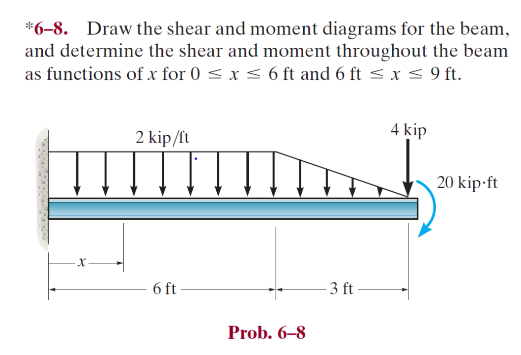
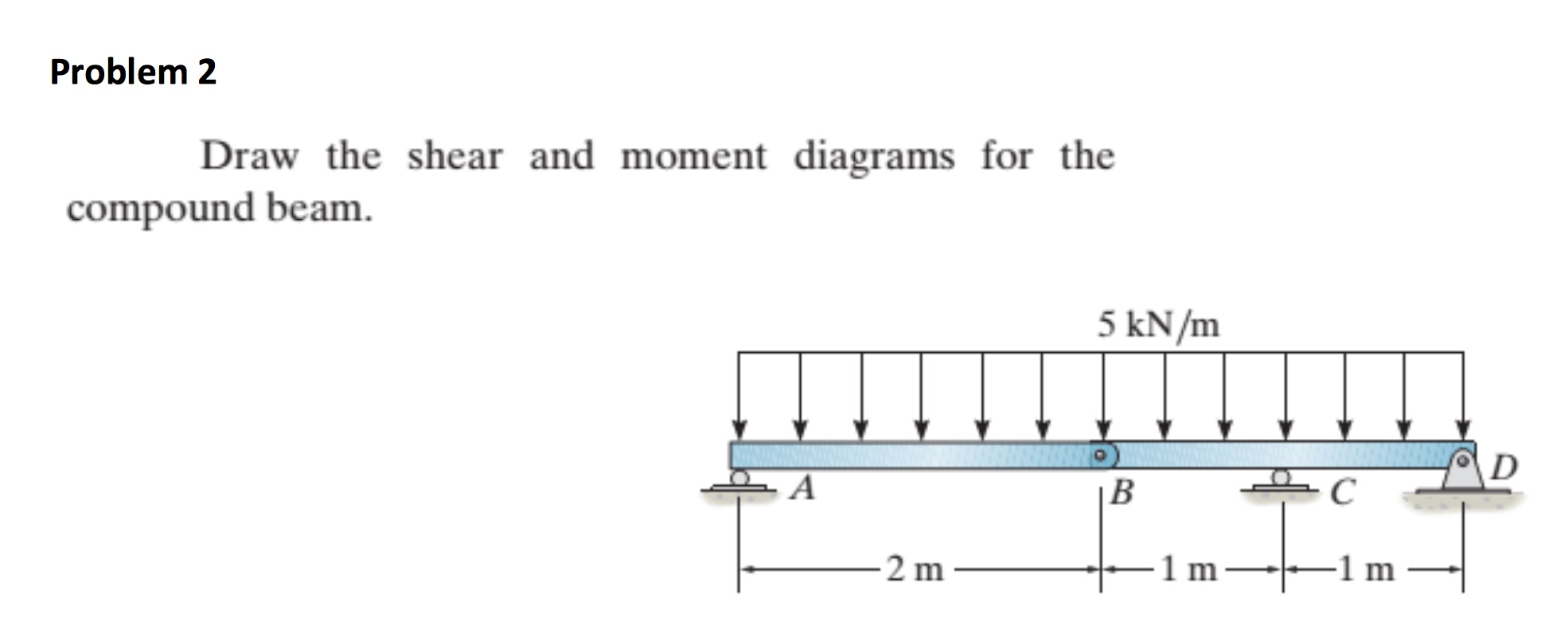
Solved Draw the shear and moment diagrams for the beam (a)

Learn How To Draw Shear Force And Bending Moment Diagrams Engineering

Mechanics Map Shear and Moment Diagrams
Understanding Shear Force and Bending Moment Diagrams The Efficient
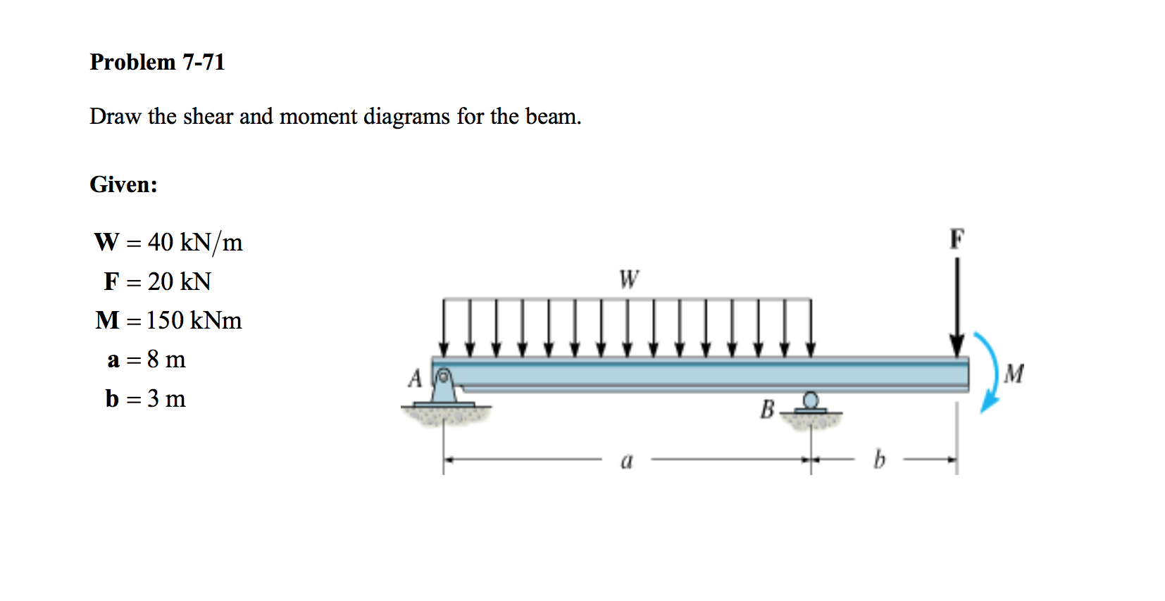
Solved Draw the shear and moment diagrams for the beam.

Drawing Shear and Moment Diagrams for Beam YouTube

Shear force and bending moment diagrams for beams pdf

Solved Draw the shear and moment diagrams for the beam
Solved Draw The Shear And Moment Diagrams For The Beam, A...
draw the shear and moment diagrams for the beam chegg
291K Views 2 Years Ago Engineering Statics.
Once These Are Determined, Derive The Shear And Moment Functions.
Beams Are Long And Slender Structural Elements, Differing From Truss Elements In That They Are Called On To Support Transverse As Well As Axial Loads.
Our Calculator Generates The Reactions, Shear Force Diagrams (Sfd), Bending Moment Diagrams (Bmd), Deflection, And Stress Of A Cantilever Beam Or Simply Supported Beam.
Related Post: