Centerline Definition Engineering Drawing
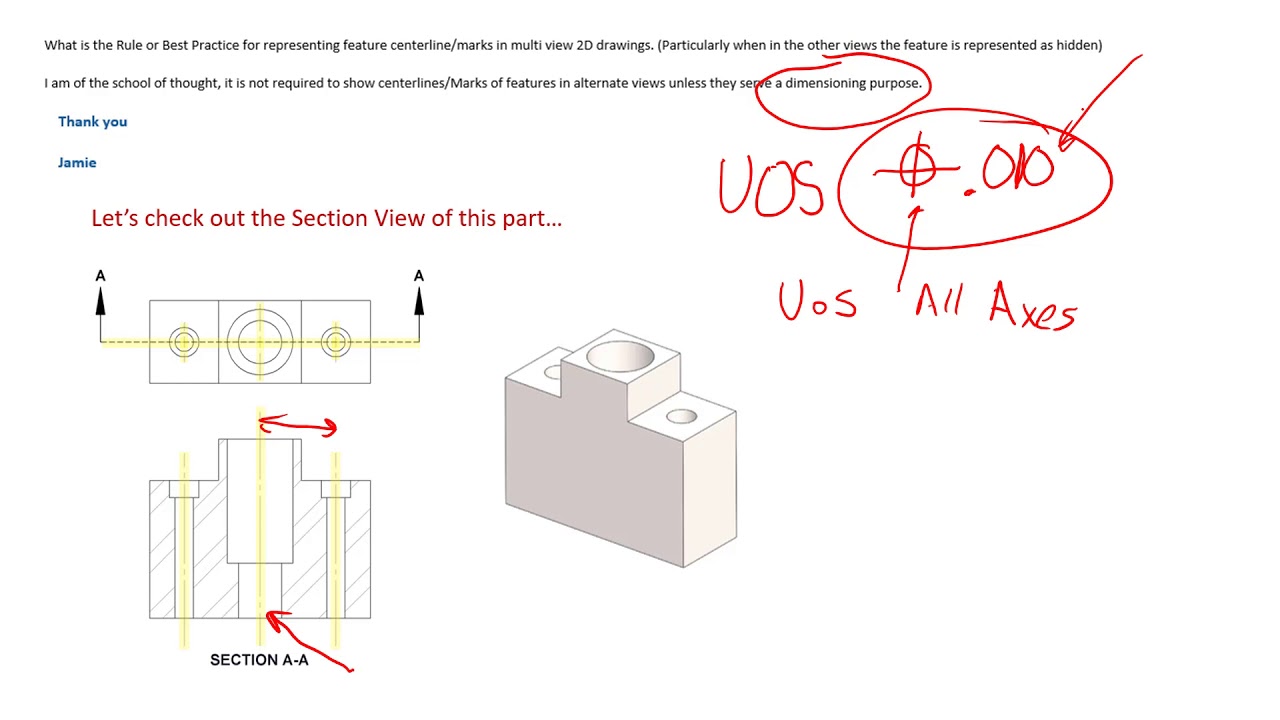
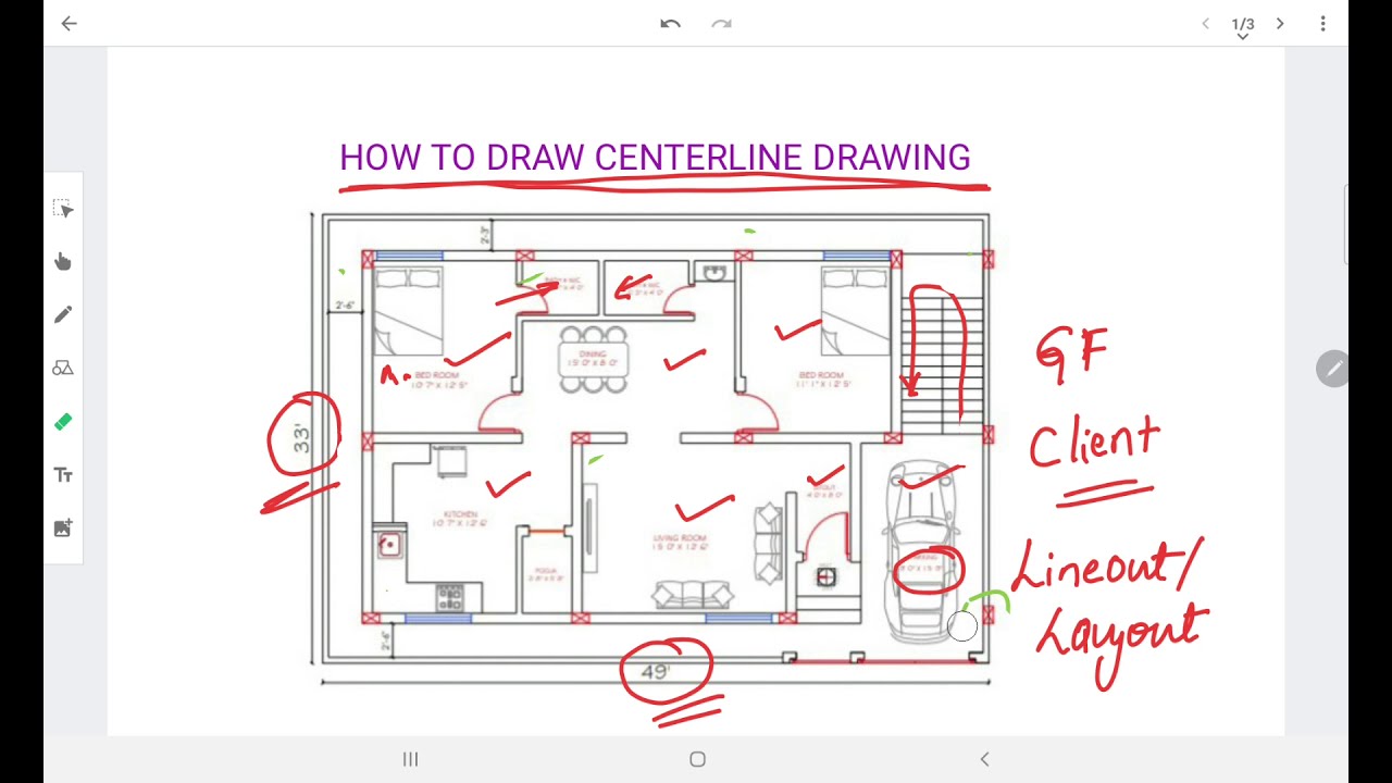
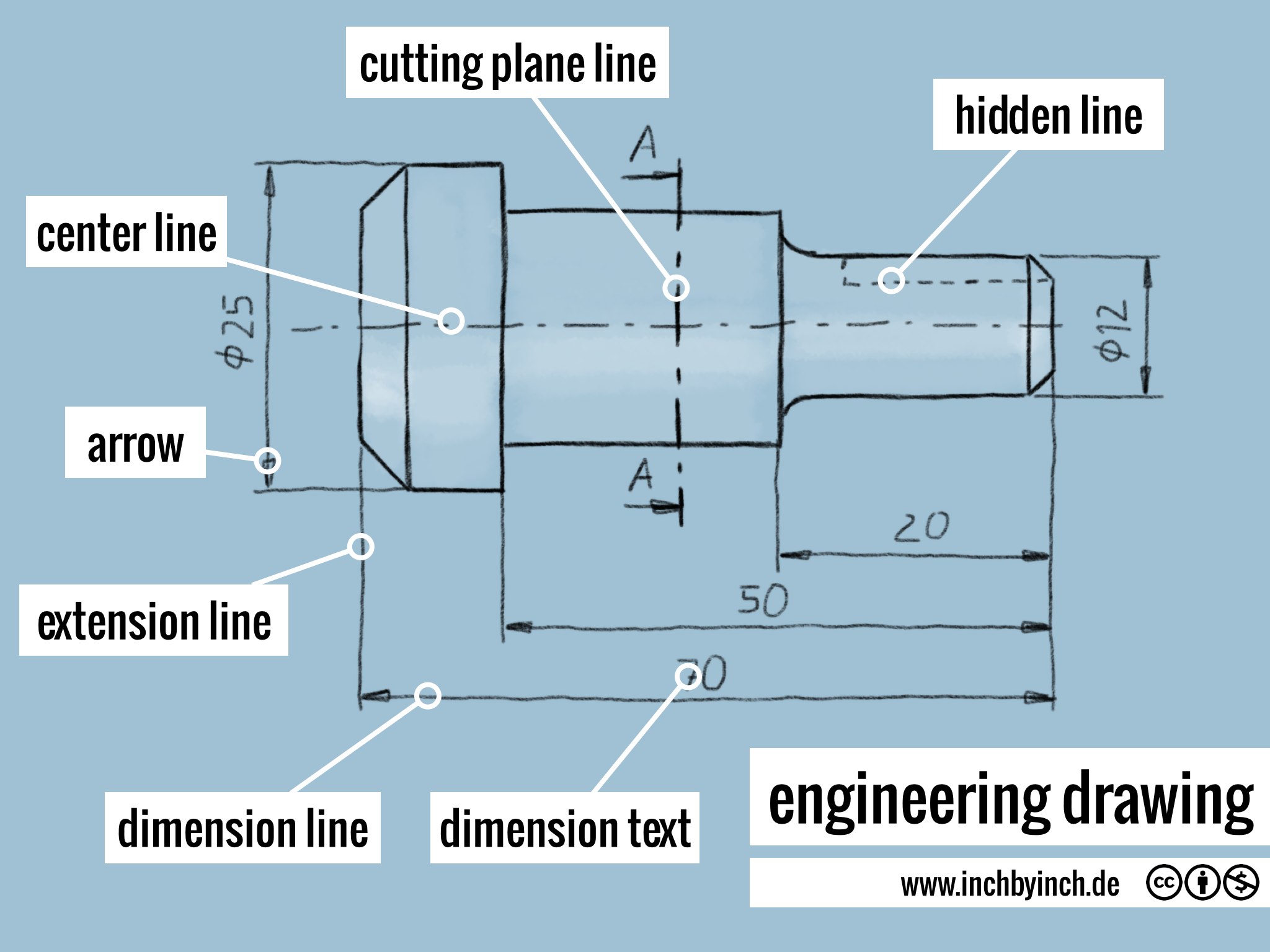
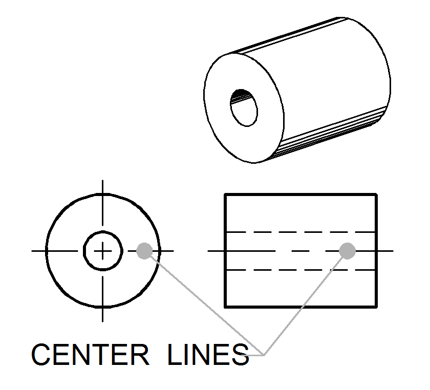
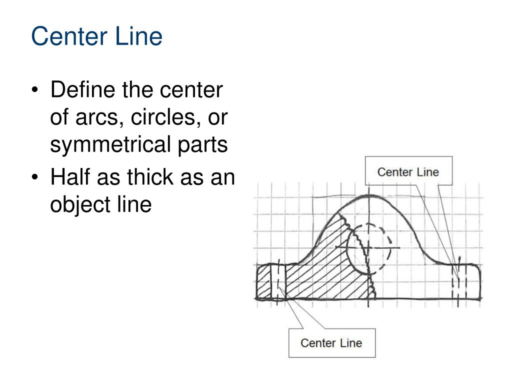
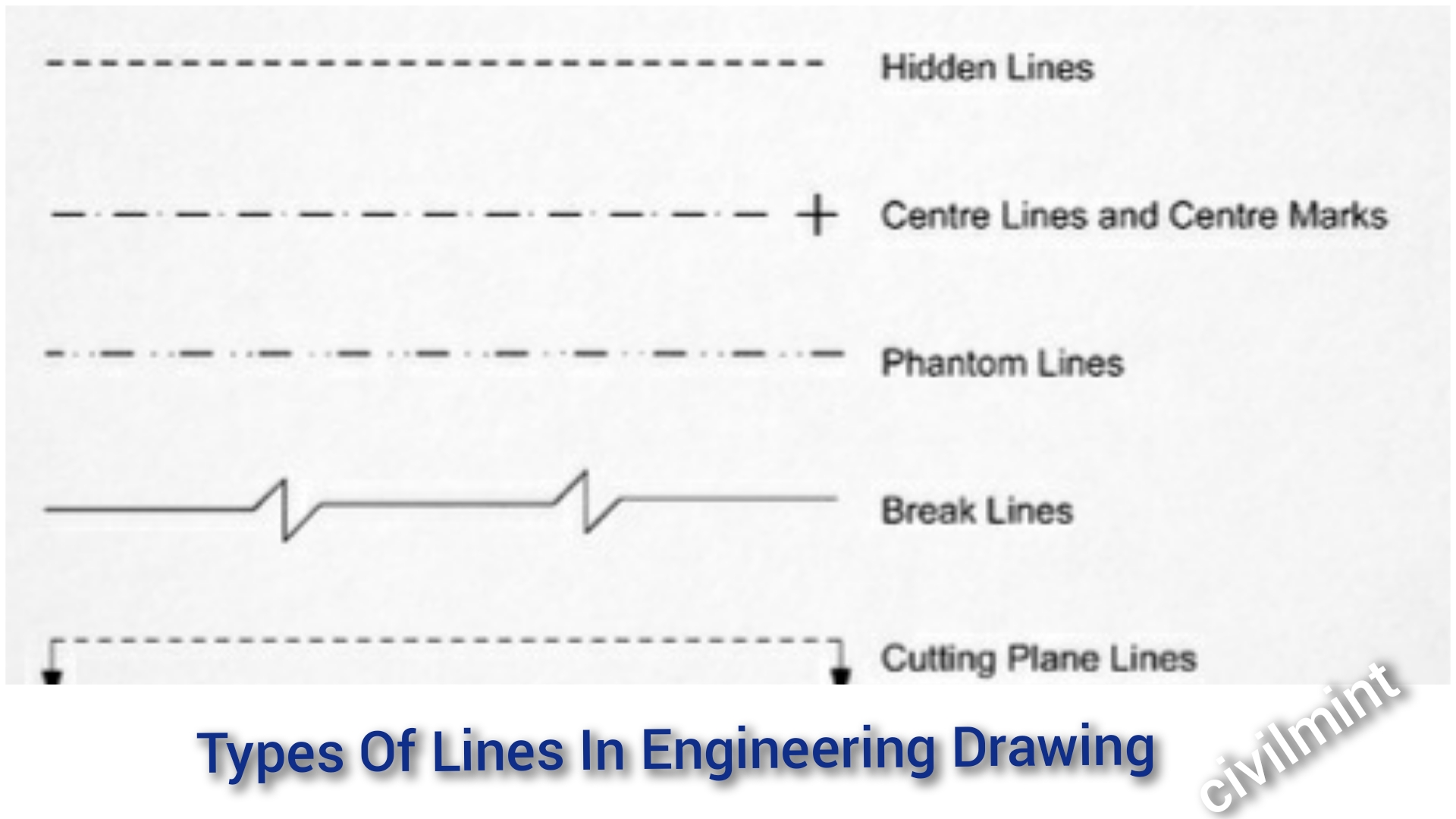
Centerline Definition Engineering Drawing - Web center lines are an important element of engineering drawings that are used to represent the axis of symmetry for a part or assembly. Web center lines show the central axis of holes and cylindrical parts. Web on drawings, centerlines are annotations that mark the centers of circles and describe their geometric size. Lb125 (mechanical) (op) 20 jul 11 09:03. Cl 1 could be either the center of the box shape (a bit ambiguous itself, what surfaces establish the centerplane) or the centerplane established by the small webs on. A complete understanding of the object should be possible from the drawing. These line types are referred to as the alphabet of lines. Web a side view of a part with a handfull of holes is much different than a side view of a plate with hundreds of holes, yet if you follow the rule that all holes are to have a centerline, you will quickly have an unreadable drawing, and those centerlines will prevent clear communication of the part definition. Each line type should exhibit a certain thickness on a finished drawing, known as line weight. When you dimension to a centerline, the extension lines will automatically shorten. If they are very small and it is not confusing, they do not have to be broken. Web on the other hand, a center line, which locates the precise center of a hole or shaft, is drawn thin and made with long and short dashes. Web center lines denote a circular feature such as a shaft or a hole. A. Engineering graphics is used in the design process for visualization, communication, and documentation. A common use is to specify the geometry necessary for the construction of a component and is called a detail drawing. Thanks in advance for any help. Web on the other hand, a center line, which locates the precise center of a hole or shaft, is drawn. When the features aren't symmetrical or equal i just dimension to the edge. Web a centerline is just a line, it may or may not mean anything. Kenat (mechanical) 20 jul 11. Engineering graphics is an effective way of communicating technical ideas and it is an essential tool in engineering design where most of the design process is graphically based.. Web on the other hand, a center line, which locates the precise center of a hole or shaft, is drawn thin and made with long and short dashes. Web what are centerlines? [ post deleted] thetick (mechanical) 13 apr 21 17:17. You can find the list of common engineering drawing abbreviations. A real or imaginary line that is equidistant from. Web a side view of a part with a handfull of holes is much different than a side view of a plate with hundreds of holes, yet if you follow the rule that all holes are to have a centerline, you will quickly have an unreadable drawing, and those centerlines will prevent clear communication of the part definition. These lines. A complete understanding of the object should be possible from the drawing. Lb125 (mechanical) (op) 20 jul 11 09:03. When the features aren't symmetrical or equal i just dimension to the edge. Web engineering working drawings basics. Each line type should exhibit a certain thickness on a finished drawing, known as line weight. This makes it easily distinguishable from the visible line. Center lines can show the position of related holes or or other cylindrical elements. In your example, cl 3, 4 and 5 i would interpret as the centerplanes of the features associated with them. A common use is to specify the geometry necessary for the construction of a component and is. Thin chain line with thick ends. You can find the list of common engineering drawing abbreviations. A common use is to specify the geometry necessary for the construction of a component and is called a detail drawing. Kenat (mechanical) 20 jul 11. Engineering graphics is an effective way of communicating technical ideas and it is an essential tool in engineering. Web 13 apr 21 16:18. A complete understanding of the object should be possible from the drawing. I only use this method of dimensioning when the features dimensioned are equal distance apart from the centreline and to the edge. Break lines are used to show where an object is broken to save drawing space or reveal interior features. Web center. Web this drawing is symmetric about the horizontal centerline. The thickness relates to the importance of the line on a drawing. Lb125 (mechanical) (op) 20 jul 11 09:03. These lines are drawn as long, thin dashed lines and are used to indicate the center point of cylindrical features, such as. They can be used to show the position of more. Thin chain line with thick ends. Engineering graphics is an effective way of communicating technical ideas and it is an essential tool in engineering design where most of the design process is graphically based. When you dimension to a centerline, the extension lines will automatically shorten. Their basic purpose is to show circular/cylindrical features in a drawing, which are found in abundance in mechanical parts. Often this line is used as a point of reference on engineering drawings. A real or imaginary line that is equidistant from the surface or sides of something. Web center lines are an important element of engineering drawings that are used to represent the axis of symmetry for a part or assembly. Kenat (mechanical) 20 jul 11. Web the thin chain line is used to indicate center lines, the lines of symmetry and also trajectories. A rectangular feature seen on an elevation of a drawing could be identified either as a circular feature or a rectangular feature. Sectional cutting planes are indicated with a thin chain line with thick ends. We can dimension directly to the centerline, as in figure 31. Engineering graphics is used in the design process for visualization, communication, and documentation. Centerlines are one of the most frequently used tools in engineering drawing. If the isometric drawing can show all details and all dimensions on one drawing, it is ideal. Each line type should exhibit a certain thickness on a finished drawing, known as line weight.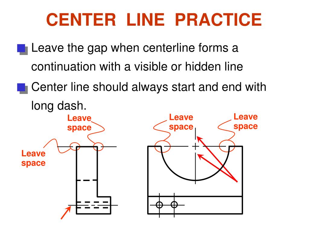
PPT Engineering Drawing Lecture 5 PROJECTION THEORY PowerPoint

PPT Orthographic Projection PowerPoint Presentation ID466828
Centerlines on Engineering Drawings and how they should be used

2020 Drawing Center Lines for an Orthographic Drawing YouTube
HOW TO PREPARE CENTERLINE DRAWING YouTube
INCH Technical English engineering drawing
Center Lines ToolNotes
PPT Line Conventions PowerPoint Presentation, free download ID2841078
Types Of Lines In Engineering Drawing

SIEMENS NX DRAFTING 7 CENTERLINE (Circular, Bolt Circle, Symmetrical
Web On The Other Hand, A Center Line, Which Locates The Precise Center Of A Hole Or Shaft, Is Drawn Thin And Made With Long And Short Dashes.
This List Includes Abbreviations Common To The Vocabulary Of People Who Work With Engineering Drawings In The Manufacture And Inspection Of Parts And Assemblies.
Thanks In Advance For Any Help.
A Common Use Is To Specify The Geometry Necessary For The Construction Of A Component And Is Called A Detail Drawing.
Related Post: