Break Lines Engineering Drawing
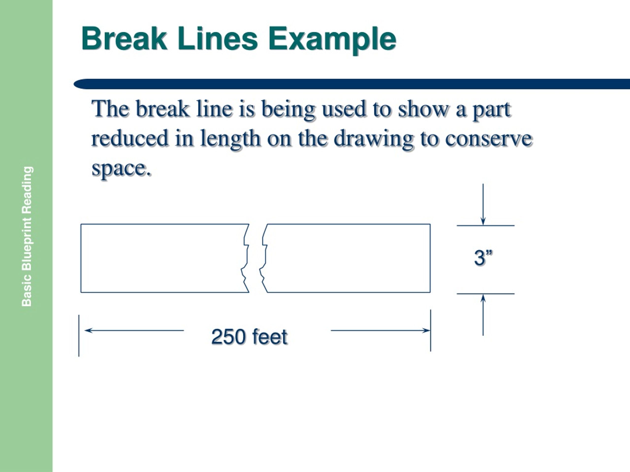
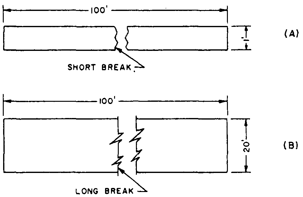
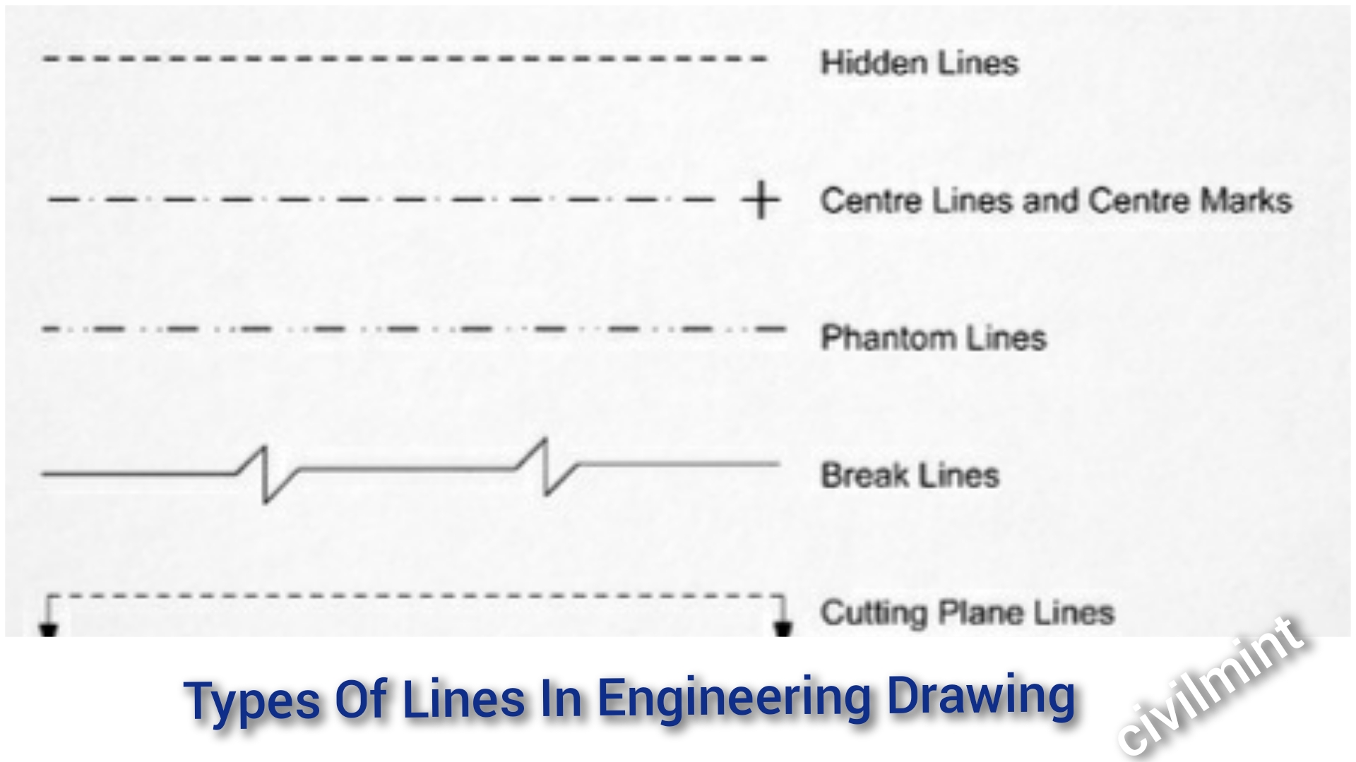
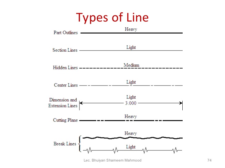
Break Lines Engineering Drawing - Break lines are used to show imaginary breaks in objects. Web freehand lines shows breaks or cuts in parts or assemblies. Rectangular break line adds a rectangular break line to a drawing when two points are picked in a drawing view. Curved lines (arcs, circles, and ellipses) cutting plane lines. Hidden lined (thick) hidden lined (thick) type lines consist of thick short dashes, closely and evenly spaced. Web engineering drawings (aka blueprints, prints, drawings, mechanical drawings) are a rich and specific outline that shows all the information and requirements needed to. Visible lines are dark and thick. Web break lines are drawn to show that a part has been shortened to reduce its size on the drawing. They are 0.6 mm thick. By manufacturinget.org / july 28, 2011. We will treat “sketching” and “drawing” as one. Line types (see also asme y14.2m) when you are preparing drawings, you will use different types of. Web break lines break lines are used to break out sections for clarity or for shortening a part. They are 0.6 mm thick. The purpose is to convey all the information necessary for manufacturing a. The purpose is to convey all the information necessary for manufacturing a product or a part. These lines are drawn to represent hidden or invisible edges of the objects. Web break lines break lines are used to break out sections for clarity or for shortening a part. They are 0.6 mm thick. This line is used to show long break. Drawings can range from very simple, with just a few dimensions, to extremely complex, with multiple. This line is used to show long break. Web we’ll break down this process into two key focus areas: A break line is usually. Web clear up your drawings in solidworks with break lines. i have described each type of line briefly. Web break lines the size of the graphic representation of an object is often reduced (usually for the purpose of economizing on paper space) by the use of a device called a break. Web clear up your drawings in solidworks with break lines. Web engineering drawings (aka blueprints, prints, drawings, mechanical drawings). The edge of the partial or interrupted view is indicated with a freehand line. We will treat “sketching” and “drawing” as one. By manufacturinget.org / july 28, 2011. Line types (see also asme y14.2m) when you are preparing drawings, you will use different types of. Visible lines are dark and thick. Web clear up your drawings in solidworks with break lines. Visible lines are dark and thick. Rectangular break line adds a rectangular break line to a drawing when two points are picked in a drawing view. Curved lines (arcs, circles, and ellipses) cutting plane lines. The edge of the partial or interrupted view is indicated with a freehand line. Drawings can range from very simple, with just a few dimensions, to extremely complex, with multiple. Rectangular break line adds a rectangular break line to a drawing when two points are picked in a drawing view. Web clear up your drawings in solidworks with break lines. Web engineering drawings (aka blueprints, prints, drawings, mechanical drawings) are a rich and specific. Web break lines the size of the graphic representation of an object is often reduced (usually for the purpose of economizing on paper space) by the use of a device called a break. Web engineering drawings (aka blueprints, prints, drawings, mechanical drawings) are a rich and specific outline that shows all the information and requirements needed to. Drawings can range. Web we’ll break down this process into two key focus areas: Web break lines are drawn to show that a part has been shortened to reduce its size on the drawing. Drawings can range from very simple, with just a few dimensions, to extremely complex, with multiple. Web the purpose of this guide is to give you the basics of. Web freehand lines shows breaks or cuts in parts or assemblies. Web break lines the size of the graphic representation of an object is often reduced (usually for the purpose of economizing on paper space) by the use of a device called a break. Web clear up your drawings in solidworks with break lines. A break line is usually. Web. Web the purpose of this guide is to give you the basics of engineering sketching and drawing. The two variations of break lines common to blueprints are the. Web this line is used to show short break or irregular boundaries. Web freehand lines shows breaks or cuts in parts or assemblies. Web break lines the size of the graphic representation of an object is often reduced (usually for the purpose of economizing on paper space) by the use of a device called a break. These lines are drawn to represent hidden or invisible edges of the objects. This tool is included with the. Break lines are used to show imaginary breaks in objects. Web clear up your drawings in solidworks with break lines. Visible lines are dark and thick. A break line is usually. Web we’ll break down this process into two key focus areas: The edge of the partial or interrupted view is indicated with a freehand line. We will treat “sketching” and “drawing” as one. Web break lines break lines are used to break out sections for clarity or for shortening a part. Web break lines break lines are used to indicate a break in the drawing, typically when it is necessary to increase the scale of a drawing while still showing the.
short break line drawing examples pdf

PPT BASIC BLUEPRINT READING PowerPoint Presentation, free download

Engineering Drawing 2 Ch4 Conventional break YouTube

How to draw a break line

Types Of Lines In Engineering Drawing

10 Different Types of Lines Used In Engineering Drawing

Different Types of LINES in Engineering Drawing//Classification of

Engineering Drawing 8 Tips to Improve Engineering Drawing Skills

AUTOCAD 2020 BREAKLINE SYMBOL HOW TO DRAW BREAK LINE SYMBOL YouTube

Types of Lines Engineering Drawing MechGate YouTube
Web An Engineering Drawing Is A Subcategory Of Technical Drawings.
By Manufacturinget.org / July 28, 2011.
The Line Type Is Usually Continuous And The Line Weight Is Thin (0.3 Mm).
Web Break Lines Are Drawn To Show That A Part Has Been Shortened To Reduce Its Size On The Drawing.
Related Post: